Poor light module and liquid crystal display device

A liquid crystal display and backlight module technology, applied in optics, instruments, nonlinear optics, etc., can solve problems such as contamination, other component damage or contamination, component damage, etc., to simplify the replacement process and avoid damage or dirty parts dirty effect

Inactive Publication Date: 2004-10-06
AU OPTRONICS CORP
View PDF0 Cites 6 Cited by
  • Summary
  • Abstract
  • Description
  • Claims
  • Application Information

AI Technical Summary

Problems solved by technology

Thus making the replacement of the light source 118 quite time consuming
Moreover, in the process of disassembly and assembly, it may also cause damage or contamination of other components
[0008] Moreover, when the product composed of the liquid crystal display 100 module needs to replace the light source at the client, the liquid crystal display 100 module must be removed from the client product first, and then the liquid crystal display 100 module must be disassembled to replace the light source , the same is not only quite time-consuming, but also has the problem of causing damage or contamination to other components during the disassembly and assembly process

Method used


Image

  • Poor light module and liquid crystal display device
  • Poor light module and liquid crystal display device
  • Poor light module and liquid crystal display device

Examples


Embodiment Construction

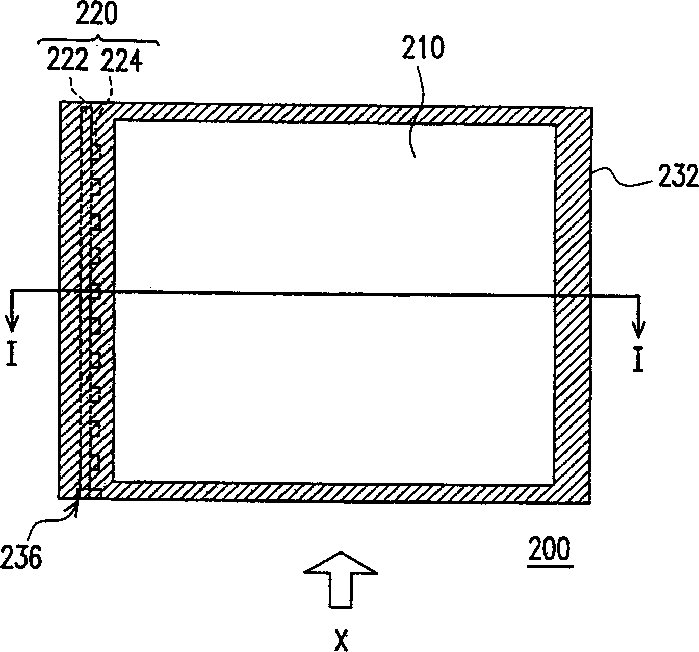
[0028] image 3 Shown is a top view of a backlight module in a preferred embodiment of the present invention, Figure 4 Illustrated is a cross-sectional view of a backlight module in a preferred embodiment of the present invention, and Figure 4 it's for image 3 Sectional view along the I-I tangent.

[0029] First, please also refer to image 3 and Figure 4 , the backlight module 200 of the preferred embodiment of the present invention at least includes a light guide plate 210 , a light source 220 and a frame 230 . Wherein, the light guide plate 210 has a light incident surface 212 , a light diffusing surface 214 and a light emitting surface 216 , and the light diffusing surface 214 may also have a plurality of V-shaped notches (not shown).

[0030] The light source 220 is arranged beside the light incident surface 212, wherein the light source 220 is, for example, a light-emitting diode array light source, and the light source 220 includes a carrier 222 and a plurality...


PUM


Abstract

A back light module and LCD is disclosed. Said back light module is composed of a light guide plate with light incidence surface, light exit surface and light diffusing surface, a light source arranged by light incidence surface, and a frame with a drawing hole on one side of carrying said light guide plate and light source.

Description

technical field [0001] The present invention relates to a backlight module (Back Light Module) and a liquid crystal display (Liquid Crystal Display, LCD), and in particular to a backlight module in which the light source can be replaced without disassembling the backlight module. group and LCD display. Background technique [0002] In order to adapt to the modern life style, the volume of video or image devices is becoming thinner and thinner day by day. Although the traditional cathode ray display (CRT) still has its advantages, due to the structure of the internal electronic cavity, the display is bulky and takes up space, and there are still problems such as radiation damage to the eyes when displaying. Therefore, flat panel displays (Flat Panel Displays), such as liquid crystal displays (LCDs), organic light-emitting displays (OLEDs), or plasma displays (Plasma Display Panels, PDPs), which are developed in conjunction with optoelectronic technology and semiconductor man...

Claims


Application Information

Patent Timeline
Patent Type & Authority Applications(China)
IPC IPC(8): G02F1/13357
Inventor 谢宗勋郭汉斌
Owner AU OPTRONICS CORP
Why Eureka
Try Eureka