Non reversible circuit element and its used wire frame and manufacturing method, communication device

A technology of circuit components and lead frames, applied in the direction of electrical components, circuits, waveguide devices, etc., can solve the problems of poor solder adhesion, rust, short circuit of circuit lines, etc., and achieve good solder adhesion and exclusive area The effect of large and small digging volume

Inactive Publication Date: 2004-10-13
ALPS ALPINE CO LTD
View PDF1 Cites 0 Cited by
  • Summary
  • Abstract
  • Description
  • Claims
  • Application Information

AI Technical Summary

Problems solved by technology

[0005] However, in the separator described in Patent Document 1, the slit is cut out from the frame part after electroplating, so the truncated surface of the slit is in a state without plating.
If there is a part that is not plated, there is a possibility that the adhesion of the solder will deteriorate during mounting and poor contact will occur.
Also, since the soft iron is exposed in the non-plated part, there is a possibility of rusting here
In addition, when the above-mentioned isolator is used as a component of a communication device, there is a risk that the generated rust will fall off and short-circuit the circuit lines in the communication device.
Moreover, in the past, the independent terminal and the grounding terminal of the isolator exceeded the outline of the frame in many cases, especially if the long side dimension of the frame was not greater than 3.5 mm, the excess of the terminal when it was installed on the circuit board could not be ignored. area, there is a problem that the installation area cannot be reduced
[0006] Furthermore, in the spacer described in Patent Document 1, the cut and raised piece is bent at 180° and the front end of the cut and raised piece is arranged in the notch of the lower frame portion, but since the depth of the notch is larger than the width, The lower frame part constituting the magnetic channel is dug deeply, which may adversely affect the offset magnetic field
Moreover, when insert molding the louvers together with the resin, since the width of the louvers is small, the contact area between the resin and the louvers is small, and there is a risk that the louvers fall off the lower frame.

Method used


Image

  • Non reversible circuit element and its used wire frame and manufacturing method, communication device
  • Non reversible circuit element and its used wire frame and manufacturing method, communication device
  • Non reversible circuit element and its used wire frame and manufacturing method, communication device

Examples


Embodiment

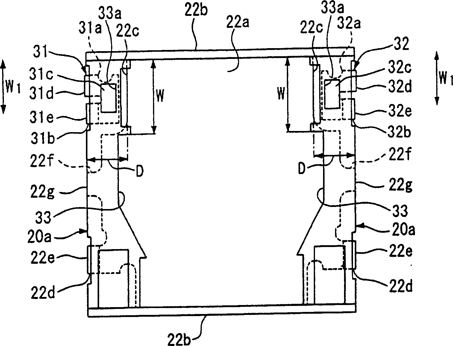
[0073] The relationship between the size of the lower frame gap and the offset magnetic field and out-of-band attenuation of the plate-shaped magnetic body is studied.

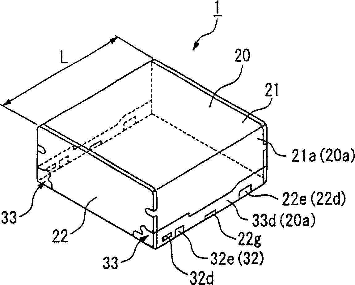
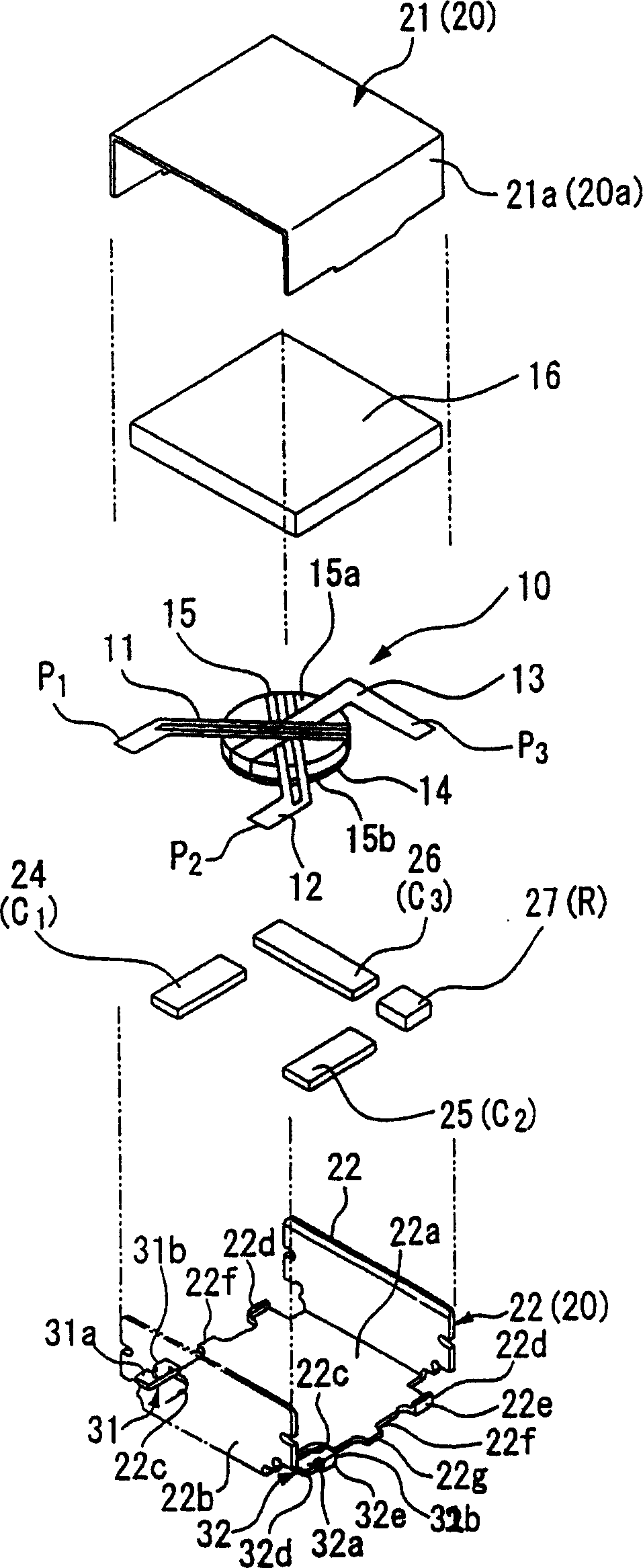
[0074] Manufactured an implementation with the same parameters as the above-mentioned embodiment except that the size of the frame is 3.2 mm, the width W of the notch is 0.9 mm, the depth D is 0.2-0.45 mm, and the width W1 in the length direction of the terminal body is 0.6 mm. example isolator. The operating frequency fo of this isolator is set to 1.88GHz. In addition, as the upper frame and the lower frame, Ag-plated pure iron with a thickness of 0.1 mm was used. As the plate-shaped magnetic body, a yttrium-iron-garnet ferrite plate that is deformed hexagonal in plan view is used. The top view shape and size of the plate-shaped magnetic body are: the length of the parallel and opposite long sides is 1.2mm, the lengths of the two opposite sides among the remaining four sides are 0.67mm and 0.98mm respective...


PUM


Abstract

Provided is an irreversible circuit element small in mounting area and having a terminal good in solderability and free from rusting. In the irreversible circuit element such as an isolator (1), a magnetic assembly having a common electrode and a center conductor attached to a plate-like magnetic material and a permanent magnet are stored in an enclosure (20) formed into a rectangular parallelepiped approximately, and dimensions (L) of the longer side of the enclosure (20) is <=3.5 mm, and an independent terminal connected to the center conductor is arranged in an outline (20a) of the enclosure (20).

Description

technical field [0001] The present invention relates to a nonreciprocal circuit element such as an isolator or a gyrator, a communication device, a lead frame for the nonreciprocal circuit element, and a method for manufacturing the nonreciprocal circuit element. Background technique [0002] A lumped constant type isolator, one of the non-reciprocal circuit components, is a high-frequency component that allows signals to pass through without loss in the direction of transmission and prevents signals from passing in the opposite direction. It is used in mobile communications such as portable phones. The transmission circuit part of the device. Such an isolator is constituted, for example, by accommodating a magnetic assembly formed by attaching a common electrode and a center conductor to a plate-shaped magnetic body and a permanent magnet in a metal frame. The frame body is formed integrally with an upper frame (yoke) and a lower frame (yoke) made of soft iron. In additio...

Claims


Application Information

Patent Timeline
Patent Type & Authority Applications(China)
IPC IPC(8): H01P1/36H01P1/383H01P1/387
CPCH01P1/387
Inventor 大西人司
Owner ALPS ALPINE CO LTD
Why Eureka
Try Eureka