
Longitudinal scanning method and device in optical image system of coherent faults

A technology of optical coherence tomography and longitudinal scanning, which is applied to measurement devices, material analysis and diagnosis through optical means, to achieve the effect of avoiding dispersion problems, simple structure and good symmetry

Inactive Publication Date: 2004-10-27
SICHUAN UNIV
View PDF0 Cites 12 Cited by
  • Summary
  • Abstract
  • Description
  • Claims
  • Application Information

AI Technical Summary

Problems solved by technology

[0022] The purpose of the present invention is to overcome the defects of the above-mentioned existing longitudinal scanning technology, provide a method and device for longitudinal scanning in the optical coherence tomography system, and solve the problem that the existing micro-displacement drive mirror cannot meet the requirements of optical technology. The coherence tomography system needs to meet the requirement of longitudinal scanning depth of 2mm to 3mm, and can directly use the high-precision traditional optical element processing method to process the required optical prism, so as to realize high-speed and high-precision linear scanning, thereby improving the accuracy of measurement

Method used


Image

  • Longitudinal scanning method and device in optical image system of coherent faults
  • Longitudinal scanning method and device in optical image system of coherent faults
  • Longitudinal scanning method and device in optical image system of coherent faults

Examples


Embodiment Construction

[0041] Below in conjunction with accompanying drawing, the present invention will be further described through embodiment. But the content of the present invention is not limited to the content involved in the embodiment.

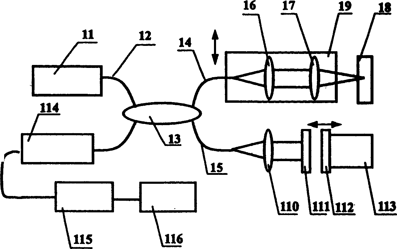
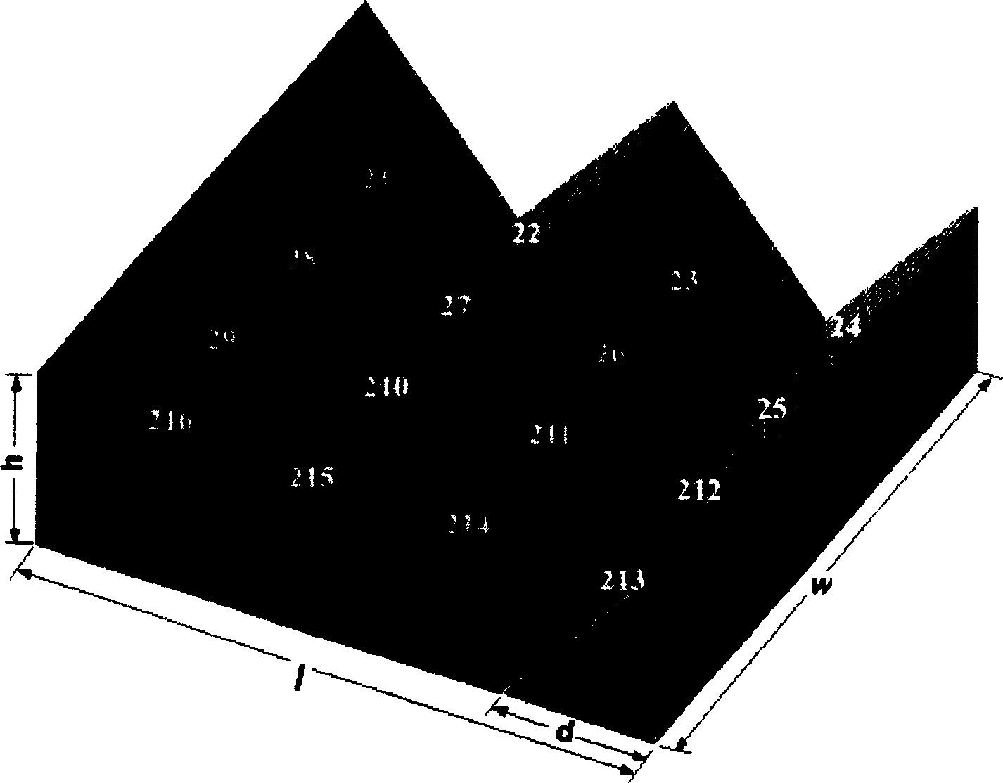
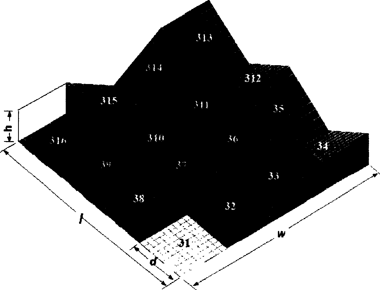
[0042] The longitudinal scanning method in the optical coherence tomography system of the present invention adopts a prism system composed of a movable prism group 112 and a stationary prism group 111, which is used in the longitudinal scanning device of the optical coherence tomography system, and then uses piezoelectric / electrostrictive The ceramic micro-displacer 113 drives the movable prism group 112 in the prism system, and high-speed and high-precision linear longitudinal scanning is realized through the translational movement of the piezoelectric / electrostrictive ceramic micro-displacer 113 .

[0043] refer to figure 1 The vertical scanning device in the optical coherence tomography system of the present invention includes components such as a light...


PUM


Abstract

A method for longitudinal scan in optically coherent tomographic imaging system features that a prism system composed of moving prism group and static prism group is used in a longitudinal scanner and a microshifting device is used to drive said moving prism group for realizing high-speed high-precision linear longitudinal scanning. Its equipment is composed of light source, optical fibre, optical fibre coupler, lens, said prism system and microshifting device.

Description

1. Technical field [0001] The invention relates to optical coherence tomography technology, in particular to a high-speed longitudinal scanning method and device thereof in an optical coherence tomography system. 2. Background technology [0002] There are mainly three types of tomographic imaging technologies that have developed relatively maturely: Computed tomography, Ultrasonic imaging and Nuclear magnetic resonance imaging. These three technologies have their own characteristics. For example, in terms of damage to the human body when they are used in human body examinations, although the dose of X-rays used for diagnosis has been reduced a lot in these years, there are still many data showing that there are relatively serious problems. Small damage effects may increase the probability of human infection of some diseases such as cancer, leukemia and cataract. However, the vast majority of data indicate no toxic effects at the diagnostic doses used today in ultrasound or...

Claims


Application Information

Patent Timeline
Patent Type & Authority Applications(China)
IPC IPC(8): A61B6/00A61B6/02G01N21/00
Inventor 高峰朱建华杜惊雷高福华郭永康
Owner SICHUAN UNIV
Learn More