
Method for testing current of bridge arm in excited power box

A technology of excitation power cabinet and current detection, which is applied in the direction of measuring current/voltage, measuring device, and measuring electrical variables, etc. It can solve the problems of difficult control system interface, difficult installation and layout, and inability to know whether the electrical components of the bridge arm are damaged or damaged To achieve the effect of easy connection, good electrical isolation effect and convenient installation

Inactive Publication Date: 2004-10-27
广州擎天电气控制实业有限公司
View PDF0 Cites 0 Cited by
  • Summary
  • Abstract
  • Description
  • Claims
  • Application Information

AI Technical Summary

Problems solved by technology

The former has no bridge arm current detection function; the latter is more difficult to install and arrange, and it is not easy to interface with the control system
And neither of them can know whether the electrical parts of the bridge arm are damaged or how damaged, so they cannot know the working status of the bridge arm

Method used


Image

  • Method for testing current of bridge arm in excited power box
  • Method for testing current of bridge arm in excited power box
  • Method for testing current of bridge arm in excited power box

Examples


Embodiment Construction

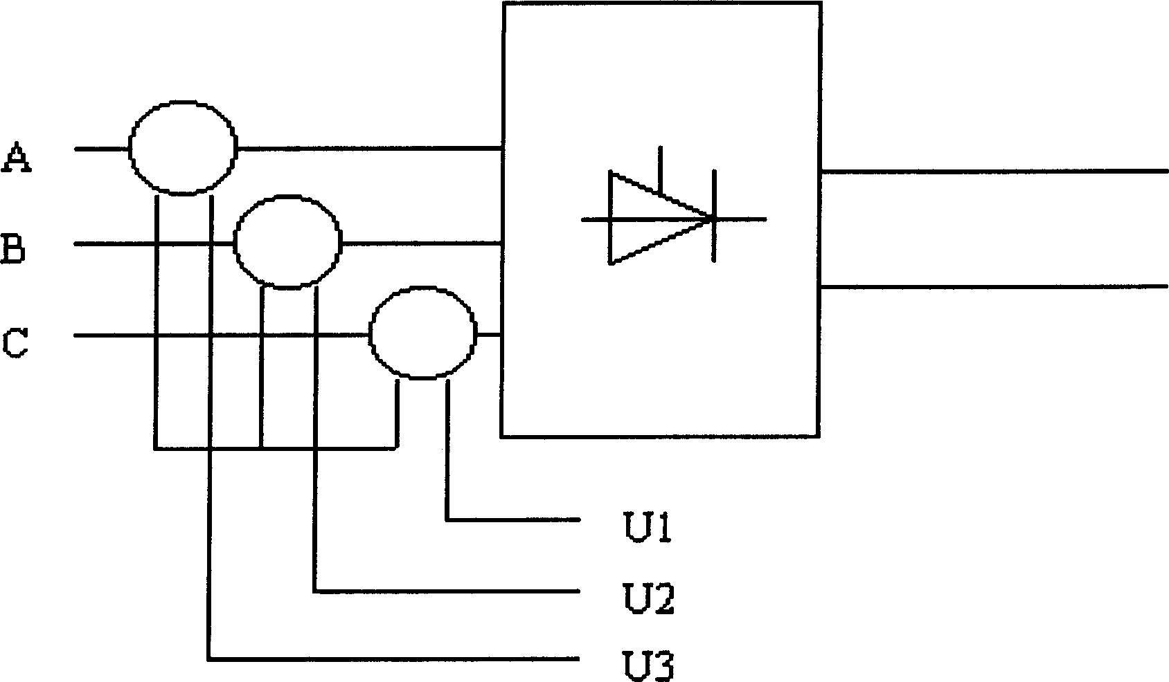
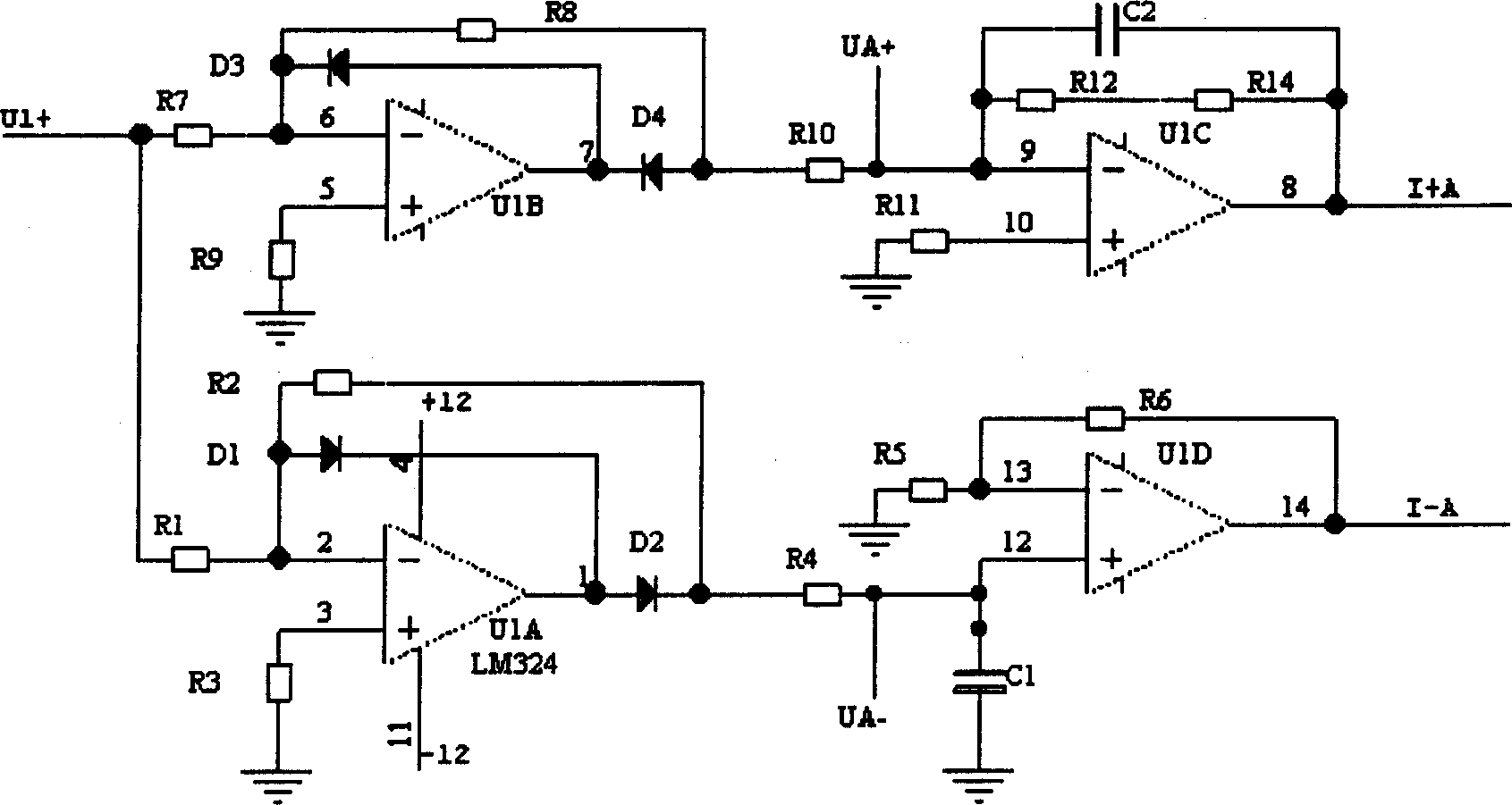
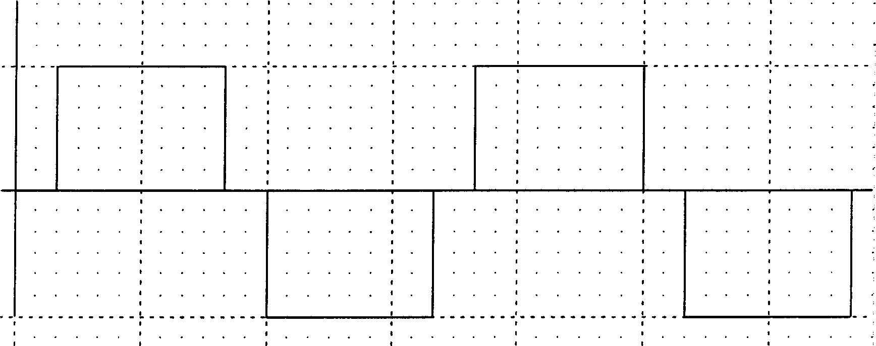
[0019] figure 1 , figure 2 , image 3 with Figure 4 This constitutes Example 1 of the present invention. From figure 1 It can be seen that it is composed of a signal acquisition unit and a waveform processing unit. The signal acquisition unit is installed on the AC side of the rectifier bridge of the excitation power cabinet, one for each of phases A, B, and C. The output end of the signal acquisition unit is connected to the input end of the waveform processing unit. The voltage signal reflecting the current of each phase of the bridge arm of A, B, C is input to the waveform processor; the signal acquisition unit is composed of a Hall transducer.

[0020] The waveform processing unit is formed by connecting operational amplifier chips U1A, U1B, U1C, U1D and their peripheral resistors R1 to R14, capacitors C1 to C2, and diodes D1 to D4. The model of the operational amplifier chip is LM324.

[0021] In this embodiment: the Hall transmitter uses the clamp-type direct detection c...


PUM


Abstract

Dedicated detection device detects AC voltages of each phase at AC side of rectification bridge in excited power box. The dedicated detection device through isolation and electromagnetic induction converts current signal to be detected to linear magnetic signal. Magnetic signal through magneto sensor is converted to linear electric signal. AC voltages detected reflect magnitude of current at bridge arm tested. The phase voltages U1, U2, U3 are converted to current signals at each bridge arm. Hall transducer is utilized as signal acquisition unit. Futures of the invention are easy of installation, easy to connect to control interface.

Description

Technical field [0001] The invention relates to a method for detecting the bridge arm current of an excitation power cabinet. It belongs to the technical field of electronic current detection equipment. Background technique [0002] In the traditional excitation power cabinet, the bridge arm current is generally not detected or a shunt is installed in the bridge arm for detection. The former has no bridge arm current detection function; the latter is difficult to install and arrange, and it is not easy to interface with the control system. Moreover, neither of them can know whether the electrical components of the bridge arm are damaged or the extent of the damage, and therefore cannot know the working state of the bridge arm. [0003] The detection method proposed by the present invention uses a Hall transducer as a detection element and is equipped with a corresponding auxiliary circuit to detect the bridge arm current, which can not only ensure the electrical isolation between...

Claims


Application Information

Patent Timeline
IPC IPC(8): G01R19/00
Inventor 李孔潮
Owner 广州擎天电气控制实业有限公司
Learn More