
Mask for vacuum deposition and organic el display panel manufactured by using the same

A display panel and mask technology, applied in the direction of electroluminescent light source, vacuum evaporation coating, electric light source, etc., can solve the fine adjustment of tension, the difficulty of removing the mask for evaporation, and the inability to change the mask for evaporation, etc. problem, achieve the effect of preventing offset and deflection

Active Publication Date: 2004-11-03
TOHOKU PIONEER CORP
View PDF1 Cites 17 Cited by
  • Summary
  • Abstract
  • Description
  • Claims
  • Application Information

AI Technical Summary

Problems solved by technology

[0007] However, in the method of fixing the vapor deposition mask on the mask frame by the conventional method, it is difficult to adjust the tension of the vapor deposition mask after the fixation. When deflection occurs due to some reasons, there are problems that cannot be corrected
[0008] In addition, it is difficult to remove the vapor deposition mask from the mask frame, and cleaning becomes troublesome. Moreover, when the mask pattern of the vapor deposition mask is changed, the vapor deposition mask cannot be changed, so that the Mask Frames for Reuse Issues
[0009] Furthermore, in the above-mentioned method called the "piercing method" used for laying the frame of the metal mask for screen printing, fine adjustment of the tension cannot be performed, so it is difficult to apply it to the organic EL display panel that requires high precision. in the vapor deposition mask

Method used

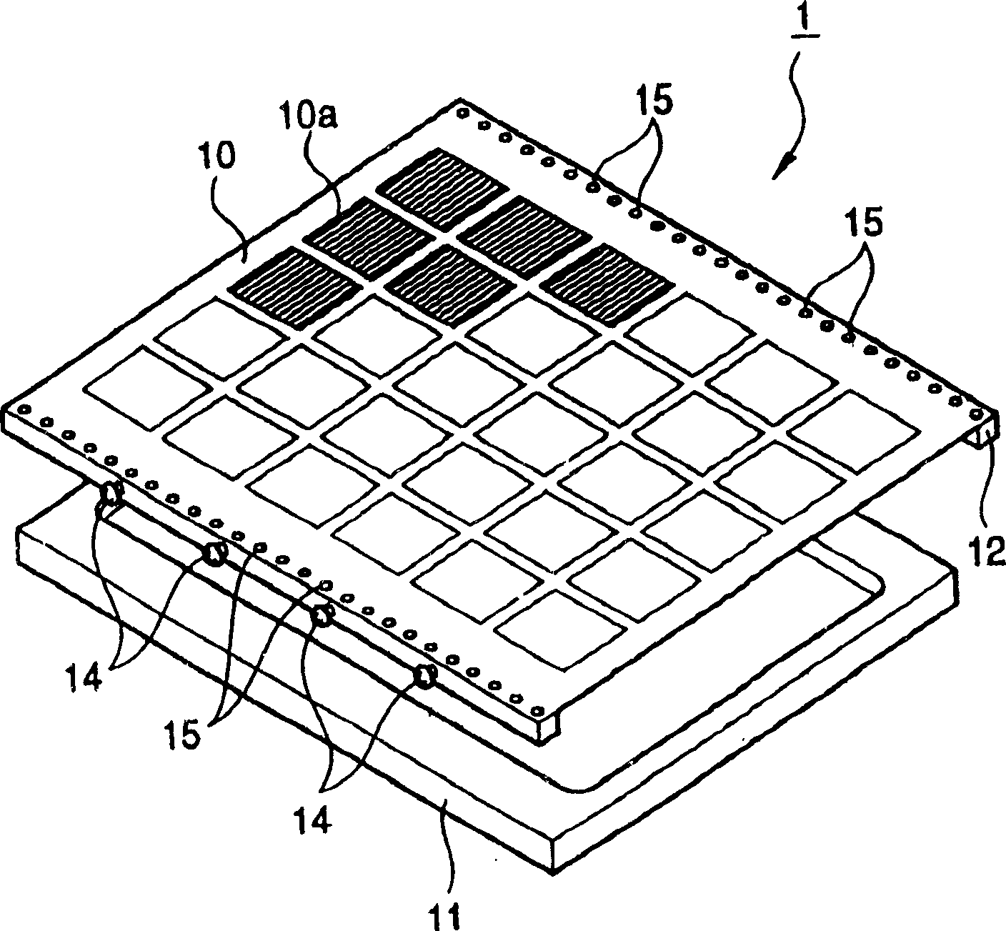
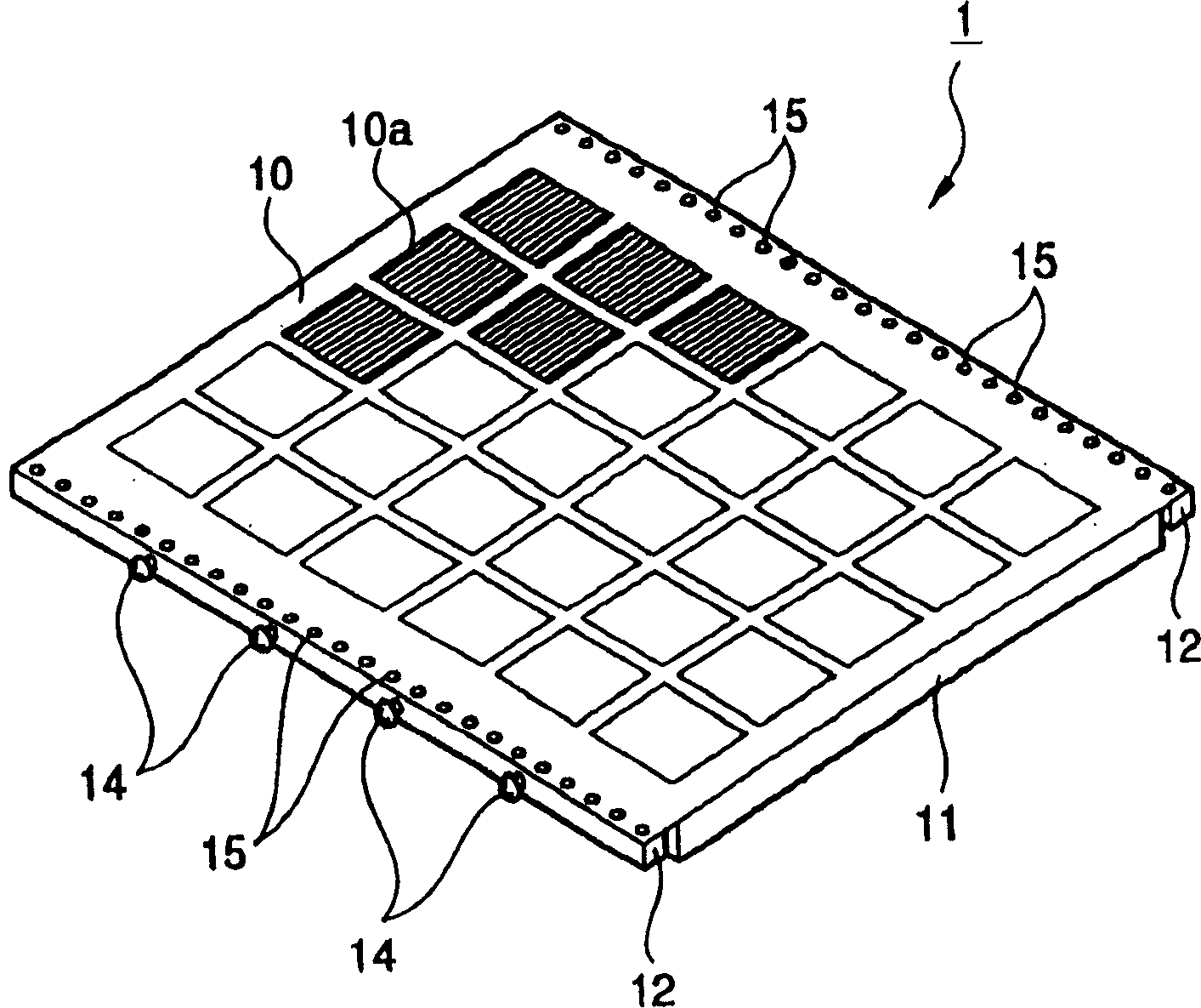

Image

  • Mask for vacuum deposition and organic el display panel manufactured by using the same
  • Mask for vacuum deposition and organic el display panel manufactured by using the same
  • Mask for vacuum deposition and organic el display panel manufactured by using the same

Examples


specific example 1

[0074] Such as Figure 6 As shown, as a fixing mechanism, strip-shaped clips 21 are placed on both ends of the mask main body 10 for evaporation along the longitudinal direction of the guide member 12 ( Figure 6 Arrow shown) is fixed in the vertical direction so that it sandwiches the mask frame 11 and the guide member 12.

specific example 2

[0076] Alternatively, use as Figure 7 The shown clips 22 are fixed vertically to the four corners of the vapor deposition mask main body 10 as indicated by arrows, and sandwich the mask frame 11 and the guide member 12 therebetween.

specific example 3

[0078] Figure 8 (a) is a perspective view showing the end of the vacuum deposition mask of Specific Example 3 of the fixing mechanism, Figure 8 (b) is Figure 8 (a) B-B line sectional view.

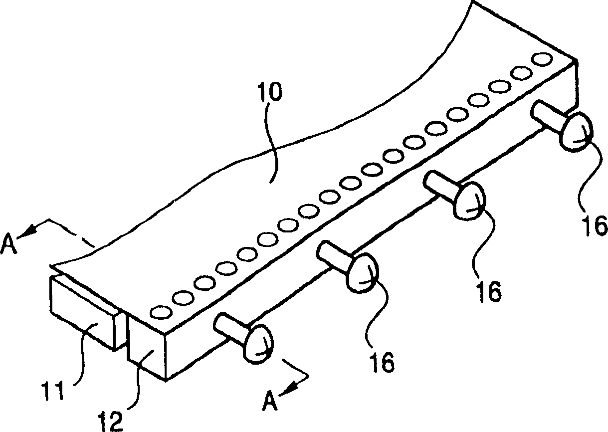
[0079] Such as Figure 8 (a) and Figure 8 As shown in (b), the fixing mechanism of specific example 3 is provided with a through hole 24 formed on the side wall of the guide member 12 and a through hole formed in the mask between the screw members 16, 16 installed on the side of the guide member 12. Holes 25 on the sides of the frame 11 are fixed in the vertical direction by inserting pins 23 through these through holes 24 and holes 25 .

[0080] In addition to the above-mentioned fixing mechanism, it is also possible to insert a screw through a through hole formed in a vertical direction relative to the mask surface of the mask frame 11 and screw its front end into the mask surface relative to the guide member 12. The guide member 12 is fixed in the vertical direction relative to...


PUM


Abstract

A mask for vacuum deposition capable of adjusting tension of a mask for vacuum deposition and easily dismounting the mask for vacuum deposition from a mask frame and an organic EL display panel are provided. A mask 1 for vacuum deposition that is held by a mask frame 11 is provided. The mask comprises a mask body 10 for vacuum deposition; a guide member 12 adhered to at least one side of the mask body 10 for vacuum deposition; a tension applying means 14 for applying predetermined tension to the mask body 10 for vacuum deposition via the guide member 12 when the guide member 12 is held by the mask frame 11; and a fixing means 21 for fixing the guide member and mask frame in the vertical direction to a mask surface.

Description

technical field [0001] The invention relates to a mask for vacuum evaporation and an organic electroluminescence (organic EL) display panel manufactured by using the mask. Background technique [0002] Recently, with the development of colorization, the minimum RGB pixel pitch of light-emitting elements such as organic EL has been miniaturized to 50 μm, and people are also studying for even smaller pixels. [0003] On the other hand, the size of the vapor deposition mask used for its production is about 400 mm to 500 mm, and it tends to become larger due to the increase in size of display panels such as organic EL. [0004] In this way, the size of the vapor deposition mask becomes larger and the mask pitch thereof becomes smaller. If the mask pitch of the enlarged vapor deposition mask becomes smaller, the rigidity of the vapor deposition mask (mask) itself decreases, and when the vapor deposition mask is fixed to the mask frame of the holding member, Since deflection occ...

Claims


Application Information

Patent Timeline
IPC IPC(8): H05B33/10C23C14/04
CPCC23C14/042C02F1/50C02F1/725B01J21/063C02F2305/10B01J35/39
Inventor 安彦浩志高桥晃
Owner TOHOKU PIONEER CORP
Learn More