Electron tube control grid

A technology for controlling grids and electron tubes, which is applied in the field of electron tubes and can solve problems such as electron beam interference

Inactive Publication Date: 2004-11-03
THALES SA
View PDF0 Cites 0 Cited by
  • Summary
  • Abstract
  • Description
  • Claims
  • Application Information

AI Technical Summary

Problems solved by technology

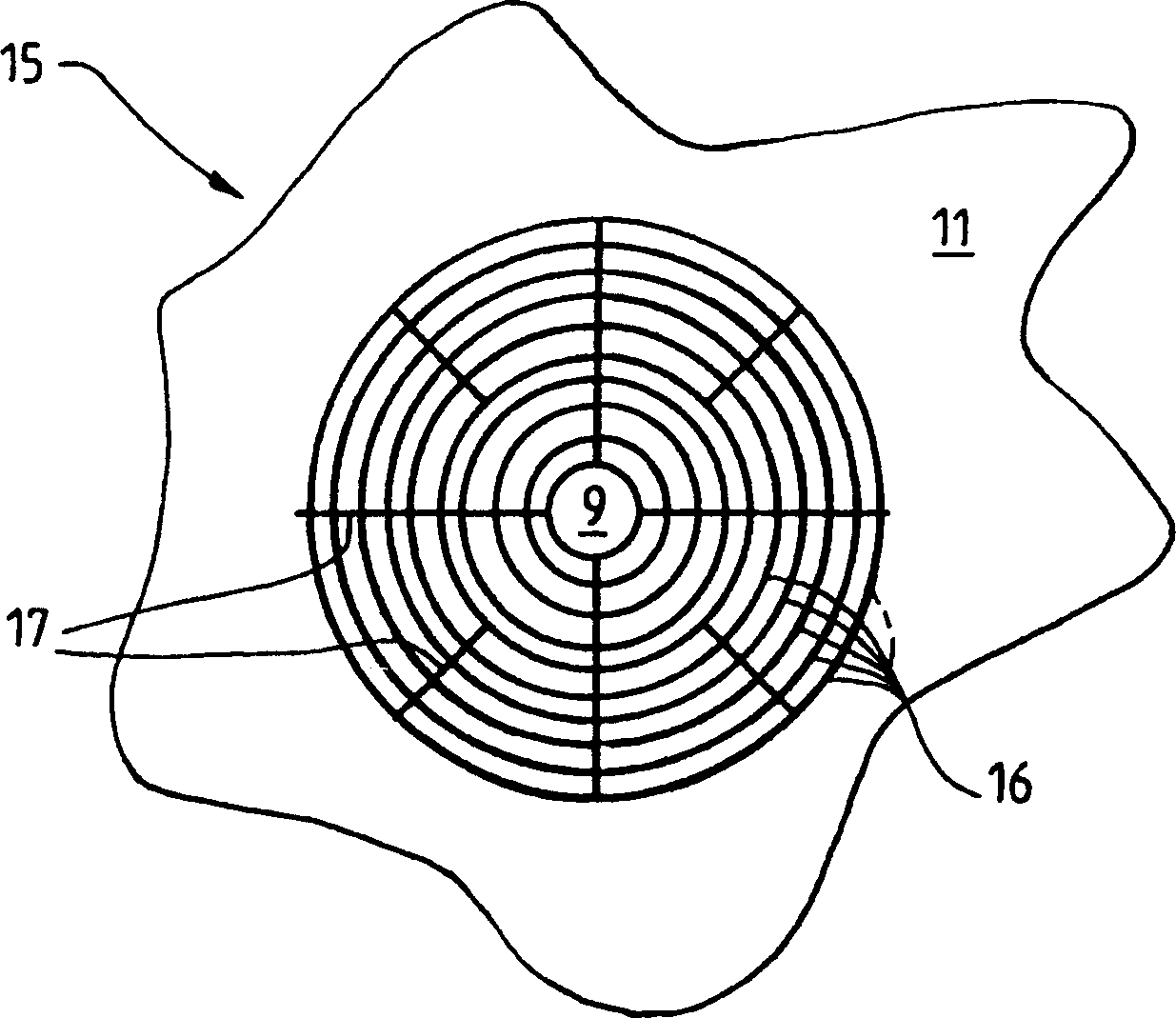
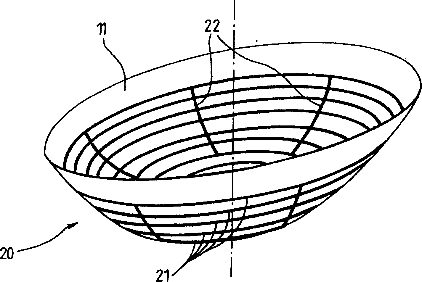
On the contrary, radial grids 17 or meridians 22 have a considerable disturbing effect on the control of electron beams

Method used


Image

  • Electron tube control grid
  • Electron tube control grid
  • Electron tube control grid

Examples


Embodiment Construction

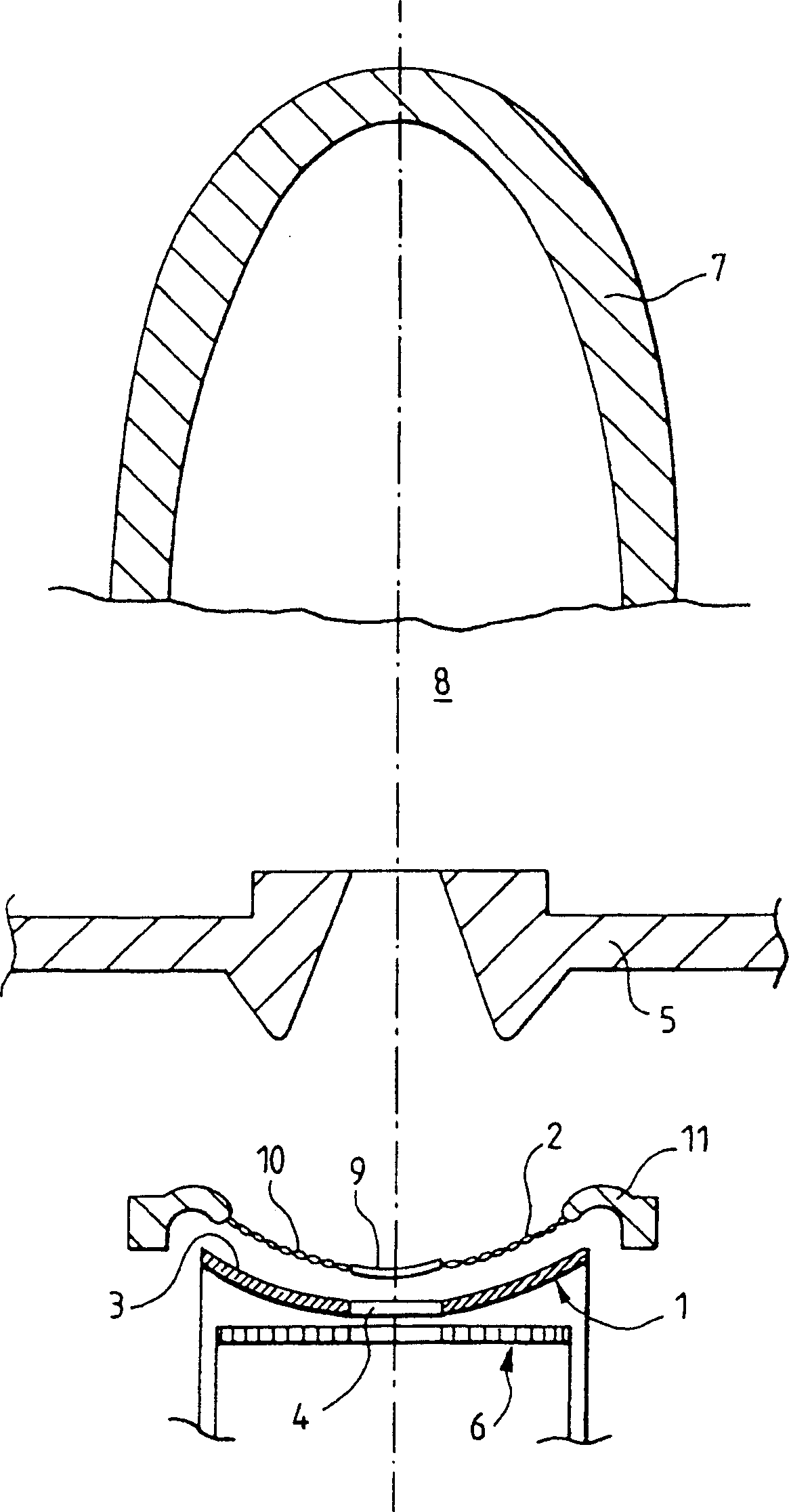
[0021] figure 1 , 2 and 3 have been further described in the above content of the present invention.

[0022] Referring to Figure 4, we may recall the definition of a curve called a "circular involute". It is the geometric locus of a point Mi on the straight line Di which is tangent to the circle C and rolls, but does not slide on the circle C. Another point Ni on the line Di describes another involute of the same circle C, which is located at a constant distance d from the first involute. In FIG. 4 the subscript i, which is a natural integer and is used for the points M and N and also the line D, indicates the different positions of the line D as it rolls around the circle C. In FIG. This rule is also used in Figure 5.

[0023] As shown in Figure 5, it can be noticed that, on circle C, the circular involute curve is consistent with the radius OA of circle C 0 The angle formed between is zero degrees, and this radius passes through the point A 0 , at point A 0 At , the ...


PUM


Abstract

The invention relates to a control grid for an electron tube. The grid has first bars that are evenly spaced out on a skewed surface and extend substantially as circle involutes about a central hub. This construction limits the bars used which make little contribution to the control of the electron beam, along with still allowing effective heat conduction through the grid.

Description

technical field [0001] The invention relates to an electron tube control grid. The field of the invention is the field of electron tubes, in particular grid-based electron tubes which operate with a longitudinal electron beam, such as inductive output tubes. In the description hereinafter, such tubes are referred to as "IOTs". It is understood that the present invention is not limited to IOT. Background technique [0002] The IOT consists of an electron gun that emits an electron beam, a resonant cavity through which the electron beam passes, and a collector that collects electrons from the electron beam at the exit of the resonant cavity. [0003] In order to understand the present invention more clearly, in figure 1 IOT is shown in, figure 1 is a longitudinal cross-sectional view of an exemplary electron tube, partially shown, and comprising a cathode 1 and a control grid 2, eg both formed as spherical segments. The cathode 1 and the control grid 2 form an electron gu...

Claims


Application Information

Patent Timeline
Patent Type & Authority Applications(China)
IPC IPC(8): H01J1/46H01J3/02H01J23/07H01J37/065
CPCH01J23/07H01J25/04H01J1/46H01J37/065H01J3/027H01J23/02
Inventor 安德烈·加比奥德米歇尔·朗格卢瓦
Owner THALES SA
Why Eureka
Try Eureka