

Saw web base body with hollowed holes
A base and hole technology, applied in the direction of circular saws, sawing equipment, stone processing tools, etc., can solve the problems of poor flatness of the base of large plane saw blades, inability to completely eliminate noise, and large cutting resistance, etc., to achieve cooling Excellent effect, reduced manufacturing cost and processing difficulty, and reduced cutting resistance
- Summary
- Abstract
- Description
- Claims
- Application Information
AI Technical Summary
Problems solved by technology
Method used
Image

Examples
Embodiment 1
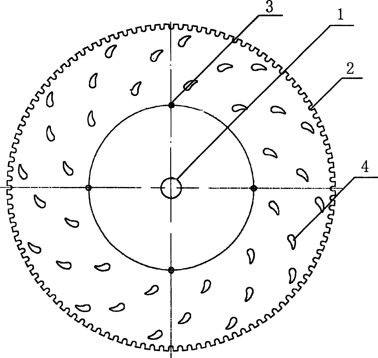
[0010] Embodiment 1: as figure 1 The hollowed-out saw blade base body with drop-shaped hollowed-out holes shown in the figure has a central installation hole 1 in the center of the base body, and water tanks 2 are evenly arranged on the outside of the base body along the circumference, and there are processing positioning holes 3 on the base body. The hollow hole 4 in the shape of a water drop is uniformly arranged on the substrate between the circumferential line where the hole center of the hole 3 is located and the circumferential line where the water tank is located. The holes 4 are hollowed out to be uniformly arranged toward the outside of the base, and the center of the processing positioning hole 3 is symmetrically positioned on the base body along the center mounting hole, and the radius is larger than the circumference of the center mounting hole 2.
Embodiment 2
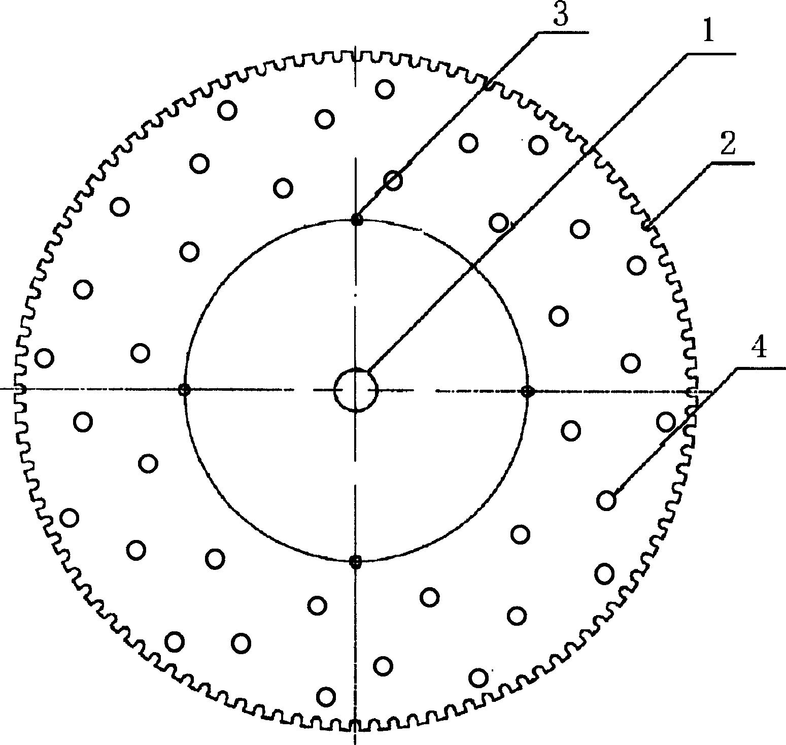
[0012] Such as figure 2 The hollowed-out hole saw blade base body shown has a circular hollowed-out hole. The center of the base base is provided with a central installation hole 1, and water tanks 2 are evenly arranged along the circumference of the base body. There are also processing positioning holes 3 on the base body. Circular hollowed holes 4 are evenly arranged on the substrate between the circumferential line where the center of the positioning hole 3 is located and the circumferential line where the water tank is located. The holes 4 are hollowed out to be uniformly arranged toward the outside of the base, and the centers of the processing positioning holes 3 are symmetrically positioned on the base body along the center mounting hole, and the radius is greater than that of the center mounting hole 1 on the circumference of the circle.
Embodiment 3
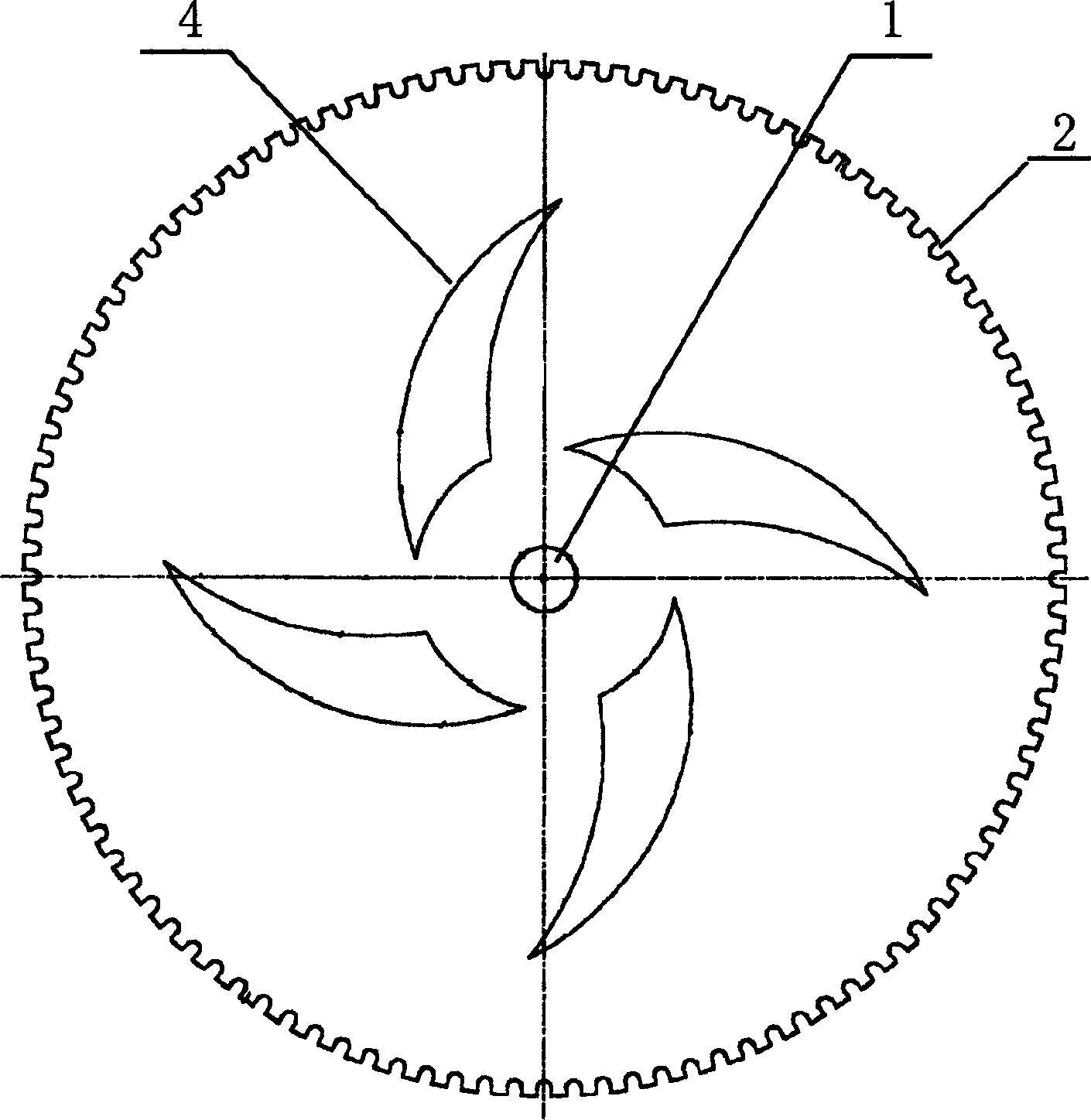
[0014] Such as image 3 The hollowed-out hole saw blade base body with sickle-shaped hollowed-out holes shown in the figure has a central installation hole 1 in the center of the base body, and water tanks 2 are arranged equidistantly along the circumference outside the base body, and sickle-shaped hollowed-out holes 4 are uniformly arranged on the base body. The empty holes 4 are arranged symmetrically along the streamline track of the water on the surface of the base body when the base body of the saw blade rotates.
[0015] Embodiment 2, Embodiment 3 and Embodiment 1 described hollow hole saw blade substrate, the material of making saw blade substrate can choose carbon structural steel and other alloy structural steel. The processing techniques of the above three embodiments are the same.
[0016] The processing technology of above-mentioned hollow hole saw blade base body is:
[0017] a. According to the type and size of the saw blade base, use flame cutting equipment an...
PUM
 Abstract
Description
Claims
Application Information