

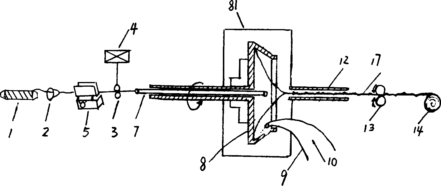
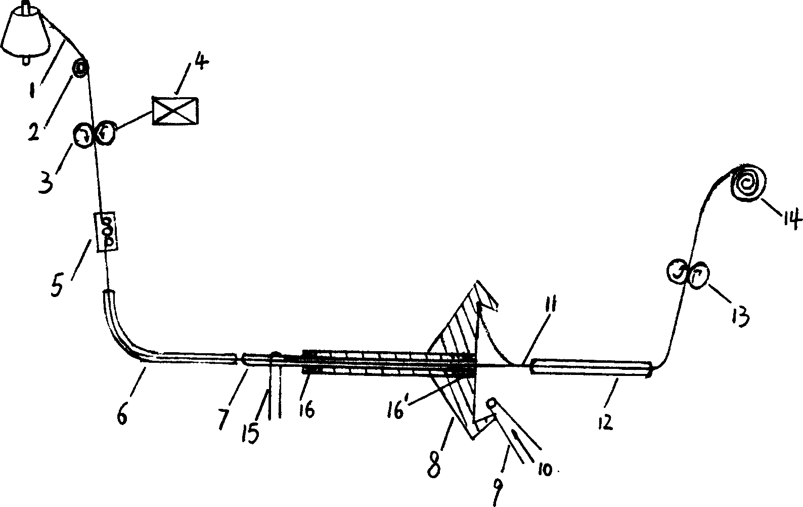
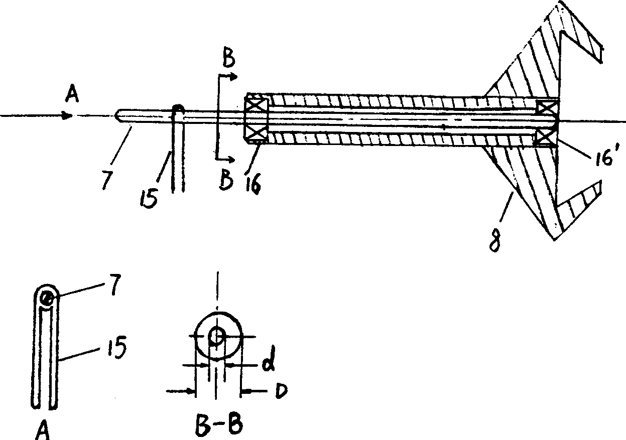
Spinning apparatus for rotor spinning composite yarn
A technology of composite yarn and rotor spinning, which is applied in yarn, textile and papermaking, etc. It can solve the problems that are difficult to realize, difficult to carry out normally, and filament winding, etc., and achieve the effect of reducing end-breakage rate and improving production efficiency
- Summary
- Abstract
- Description
- Claims
- Application Information
AI Technical Summary
Problems solved by technology
Method used
Image

Examples
Embodiment
[0039] Composite yarns with different structures and properties are spun on the rotor spinning machine of the present invention, wherein the proportion of filaments in the composite yarn is 5% to 30%:
[0040](1) When the ratio of the filament feeding speed to the yarn drawing speed of the composite yarn is 0.8, the composite yarn with a core-spun structure can be obtained, and the breaking strength of the composite yarn can be increased by 10% compared with the ordinary rotor-spun yarn with the same linear density, and the appearance is similar to that of the rotor-spun yarn. Ordinary rotor-spun yarns are similar, such as Figure 4 Figure (a) and Figure (b) in the figure;
[0041] (2) When the ratio of the filament feeding speed to the yarn drawing speed of the composite yarn is 0.98, the composite yarn with a strand structure can be obtained, and the breaking strength of the composite yarn can be increased by 5% compared with the ordinary rotor yarn with the same linear dens...
PUM
 Abstract
Description
Claims
Application Information