Microwave ultra violet light source

An ultraviolet light source and microwave technology, applied in the field of ultraviolet light source, can solve the problems of electrode ignition, low power and low efficiency, and achieve the effects of rapid ignition, high power and high efficiency

Inactive Publication Date: 2004-11-24
UNIV OF ELECTRONIC SCI & TECH OF CHINA
View PDF0 Cites 14 Cited by
  • Summary
  • Abstract
  • Description
  • Claims
  • Application Information

AI Technical Summary

Problems solved by technology

Traditional ultraviolet lamps generally have low power and low efficiency, and the ballast and starter are easily damaged. The electrodes in the ultraviolet lamp will

Method used


Image

  • Microwave ultra violet light source
  • Microwave ultra violet light source

Examples


Embodiment Construction

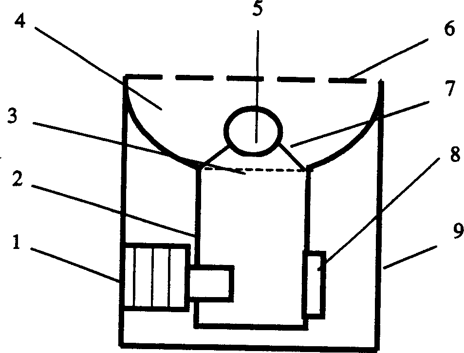
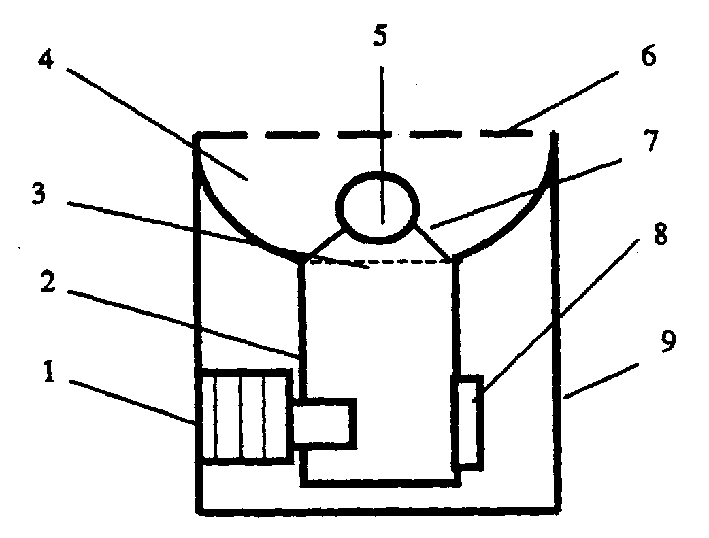
[0014] Electrodeless Microwave UV Lamp

[0015] 1kw / 2450MHz (50-1000w adjustable) microwave magnetron 1 generates microwave power of 50-1000w, the microwave is transmitted to the microwave resonant cavity 4 through the waveguide 2, and the ultraviolet lamp 5 is placed on the lamp holder 7 in the microwave resonant cavity 4 , the microwave in the microwave resonant cavity 4 passes through the shell glass of the ultraviolet lamp 5 and acts on the gas in the lamp to ionize the gas to generate plasma to emit ultraviolet light. The shell of the ultraviolet lamp 5 is made of quartz glass, and the size of the ultraviolet lamp 5 is about φ50mm spherical bulb, evacuated to 10 -3 After the Pa is filled with mercury and argon, the filling amount of mercury is 1-10 grams, and the filling amount of argon meets the working pressure of about 50-200 Pa in the lamp.


PUM


Abstract

The present invention discloses a microwave UV light source. It is composed of magnetron, microwave waveguide, microwave energy-feeding hole, microwave resonant cavity, UV lamp, microwave screening net, lamp stand, fan and base. It is characterized by that after the UV lamp is evacuated, its interior can be filled with inert gas, mercury vapour or metal halide vapour and mixture of the above-mentioned gases. Said light source can be used for implementing disinfection and sterilization of gas, liquid and solid, photochemical synthesis of chemical substance and UV etching and UV information erasion of electronic material and device.

Description

Technical field [0001] The invention belongs to the field of electronic technology, and in particular relates to an ultraviolet light source. Background technique [0002] Traditional ultraviolet lamps are composed of power supply, electrodes, ballasts, and lamp tubes (bulbs). Traditional ultraviolet lamps generally have low power and low efficiency, and the ballast and starter are easily damaged. The electrodes in the ultraviolet lamp will deteriorate over time, electrode ignition and electrode loss will occur, so the lamp The tube is easy to turn black and not bright, and its lifespan is not long. Contents of the invention [0003] The purpose of the present invention is to provide a microwave ultraviolet light source, which has the advantages of no need for electrodes, no need for ballasts and starters, high power (tens of watts to tens of kilowatts), rapid start, long life (no electrode deterioration, no Electrode loss), low energy consumption, high efficiency (light...

Claims


Application Information

Patent Timeline
IPC IPC(8): H01J65/04
Inventor 谢扩军
Owner UNIV OF ELECTRONIC SCI & TECH OF CHINA
Why Eureka
Try Eureka