Suction unit for use in an electric vacuum cleaner and electric vacuum cleaner employing same

A vacuum cleaner and vacuum head technology, applied in vacuum cleaners, suction nozzles, applications, etc., can solve problems such as electric shock, fire, and harmful by-products such as ozone

Inactive Publication Date: 2004-12-01
PANASONIC CORP
View PDF1 Cites 4 Cited by
  • Summary
  • Abstract
  • Description
  • Claims
  • Application Information

AI Technical Summary

Problems solved by technology

[0003] However, in the existing negative ion generators, if the discharge method is adopted, in addition to generating negative ions, harmful by-products, namely ozone, will also be produced simultaneously; in addition, the discharge will use a high-voltage circuit, and the high voltage will cause electric shock and fire. danger

Method used


Image

  • Suction unit for use in an electric vacuum cleaner and electric vacuum cleaner employing same
  • Suction unit for use in an electric vacuum cleaner and electric vacuum cleaner employing same
  • Suction unit for use in an electric vacuum cleaner and electric vacuum cleaner employing same

Examples


Embodiment 1

[0032] With the help of Figure 1 to Figure 9 The first embodiment of the present invention will be described.

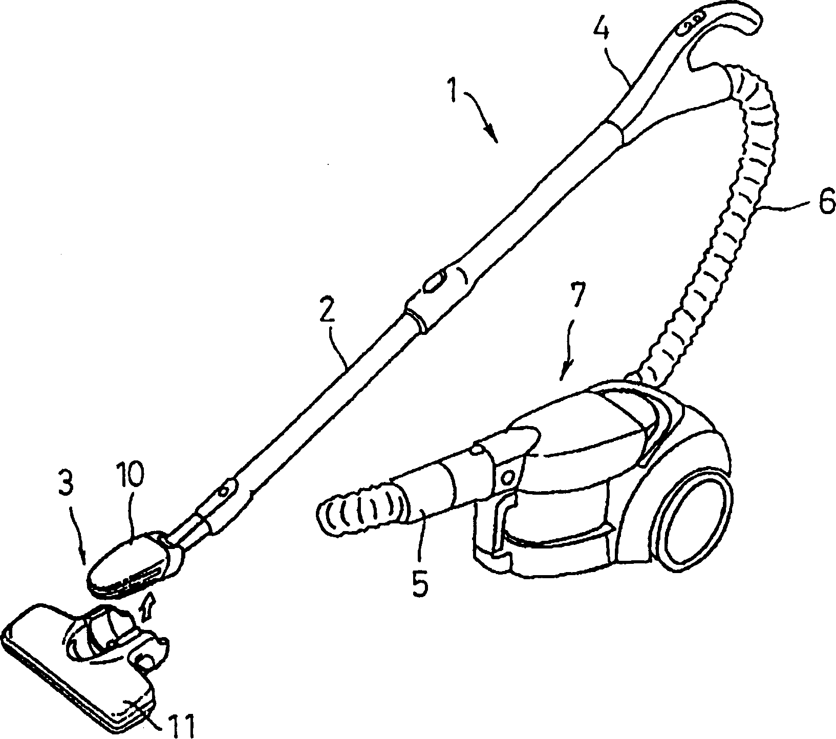
[0033] This example shows figure 1 The ground mobile electric vacuum cleaner 1 shown in and the dust suction head 3 as its dust suction port. In the electric vacuum cleaner 1, the dust suction head 3 is mounted on the front end of the extension tube 2 in a detachable manner, and the other end of the extension tube 2 is connected with the armrest handle (handrail operating rod) 4, and the soft handle extending from the armrest handle 4 The pipe 6 is connected to the main body 7 of the vacuum cleaner through a hose joint 5 .

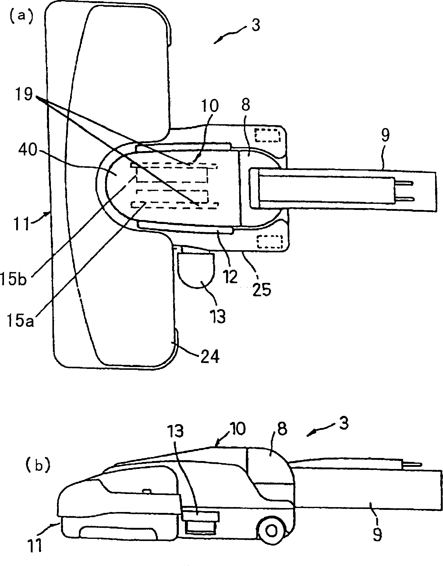
[0034] Above-mentioned suction head 3 such as figure 2 As shown in (a), (b), it consists of a floor suction head 11 and a small suction head 10 detachably mounted thereon. The small suction head 10 is provided with: a connecting pipe 9 constituting a connecting part for connecting with the extension pipe 2; The rotary coupling member (rota...

Embodiment 2

[0059] Next, use Figure 10 ~ Figure 11 The second embodiment of the present invention will be described. Here, the same constituent elements as those in the above embodiment are given the same symbols, and their descriptions are omitted.

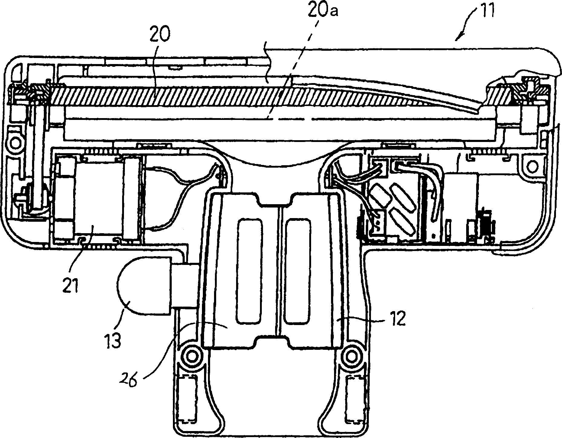
[0060] The bottom surface of small suction head 10 is as Figure 10 It is made into an arc shape as shown in , and has a plurality of openings 23 . The brush group 27 that is arranged on a base cloth 36 is housed on the bottom apex position of arc direction, and this brush group 27 is as Figure 11 have a different charge sequence as shown in . Bottom surface openings 23 are provided on both sides of the brush group 27, and the brush groups 27 are also installed on their outer sides.

[0061] The operation in the above structure is as follows.

[0062] When cleaning, the brush group 27 rubs against the surface to be cleaned. At this time, the bristles 34 made of easily positively charged material and the bristles 35 made of easily negat...


PUM


Abstract

Provided is a vacuum cleaner capable of improving the dust collecting performance by utilizing ions and enhancing the usability by easily switching the cleaning mode between a narrow space cleaning mode and a wide space cleaning mode. The suction nozzle comprises a floor nozzle 11 and a small nozzle 10 detachably mounted on the floor nozzle 10, and a suction head 40 of the small nozzle 10 is mounted on the floor nozzle 11. When the suction head 40 is mounted on the floor nozzle 11, the interior of the suction head 40 communicates with the floor nozzle 11. Both the floor nozzle 11 and the small nozzle 10 have ion generators. Dust on a floor surface can be effectively removed by the effect of ions when the small nozzle 10 is mounted on the floor nozzle 11. Further, dust on the floor surface can be effectively removed with the effect of ions when a narrow place is cleaned with the small nozzle 10 only.

Description

technical field [0001] The invention relates to a dust-absorbing head of an electric vacuum cleaner and an electric vacuum cleaner using the dust-absorbing head. Background technique [0002] In the existing negative ion generating device, generally the high voltage generated by the high voltage circuit is sparked between the electrodes separated by a certain distance, and discharge is generated between the electrodes separated by the air layer; Discharge occurs on the surface of the insulator and releases negative charges, that is, electrons, into the air, making the moisture in the air negatively charged; or irradiating ultraviolet rays on the surface of gold or platinum to drive electrons in the metal into the air, which also makes the air Moisture and the like are negatively charged to form negative ions (for details, refer to Japanese Patent Publication No. 2001-338744). [0003] However, in the existing negative ion generators, if the discharge method is adopted, in a...

Claims


Application Information

Patent Timeline
Patent Type & Authority Applications(China)
IPC IPC(8): A46B15/00A47L9/02A47L9/04A47L9/06A47L9/24
CPCA47L9/242A47L9/0613A47L9/02A47L9/06
Inventor 澁谷昌树藤田孝一副岛雅邦
Owner PANASONIC CORP
Why Eureka
Try Eureka