Aggregate dryer burner device and method

A burner, main combustion technology, applied in burners, combustion equipment, non-progressive dryers, etc., can solve the problem of ineffective combustion of heavy oil, and achieve the effect of reducing requirements, saving costs, and high energy efficiency

Inactive Publication Date: 2004-12-01
HAUKE MFG
View PDF3 Cites 1 Cited by
  • Summary
  • Abstract
  • Description
  • Claims
  • Application Information

AI Technical Summary

Problems solved by technology

A 50 Hz blower supplying air at 24osig pressure will work well with conventional stockpile dry burners using light oil, but 24osig air will not burn heavy oil efficiently

Method used


Image

  • Aggregate dryer burner device and method
  • Aggregate dryer burner device and method
  • Aggregate dryer burner device and method

Examples


Embodiment Construction

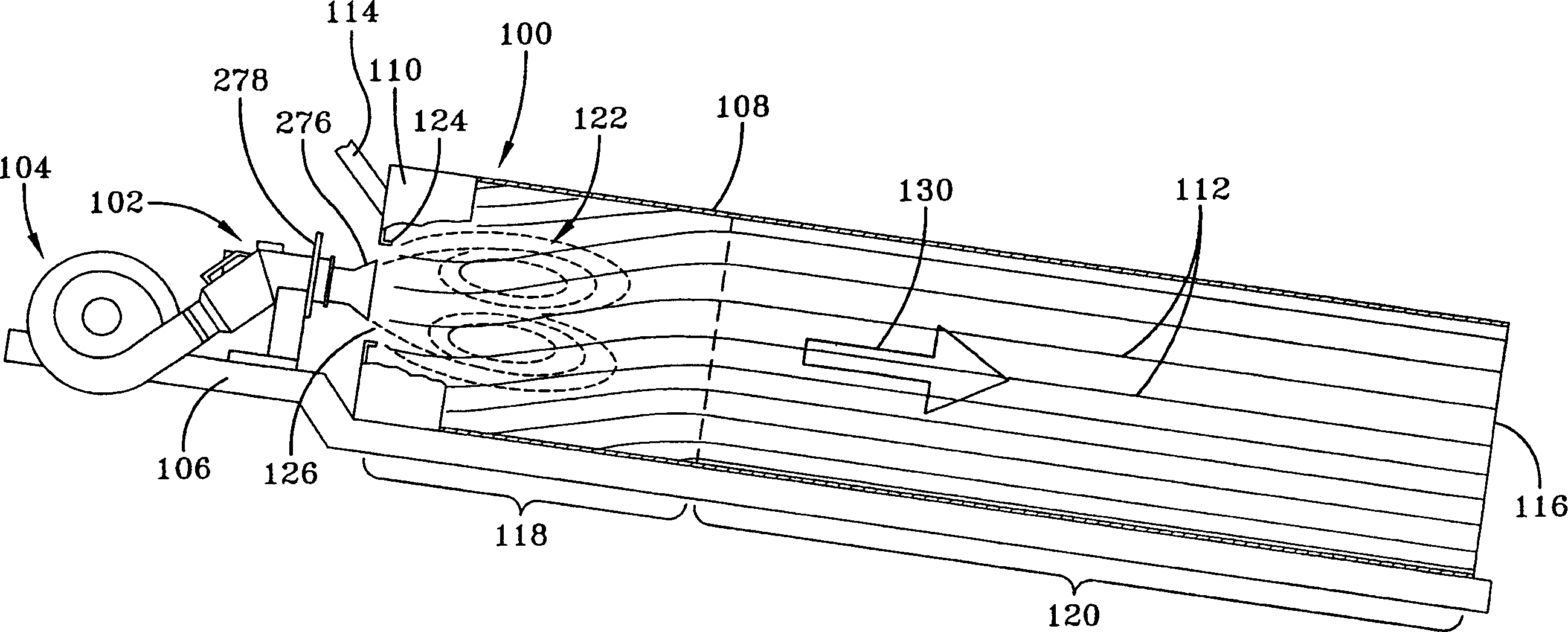
[0028] figure 1 A portable rotary stock drier 100 for drying and preheating stock mixed with petroleum-based materials in the manufacture of paving asphalt is schematically shown, heated by the burner of the present invention. The dryer 100 is heated by a burner 102 which includes a main combustion air supply such as a centrifugal blower 104 for supplying combustion air to the burner. Other types of primary combustion air supplies are readily available and are known in the art. The blower preferably produces air at a pressure in the range of approximately 22 osig to 28 osig. In the most preferred embodiment, the blower produces air at a pressure of approximately 24 osig. The dryer 100 , burner 102 and blower 104 are mounted on a suitable frame 106 .

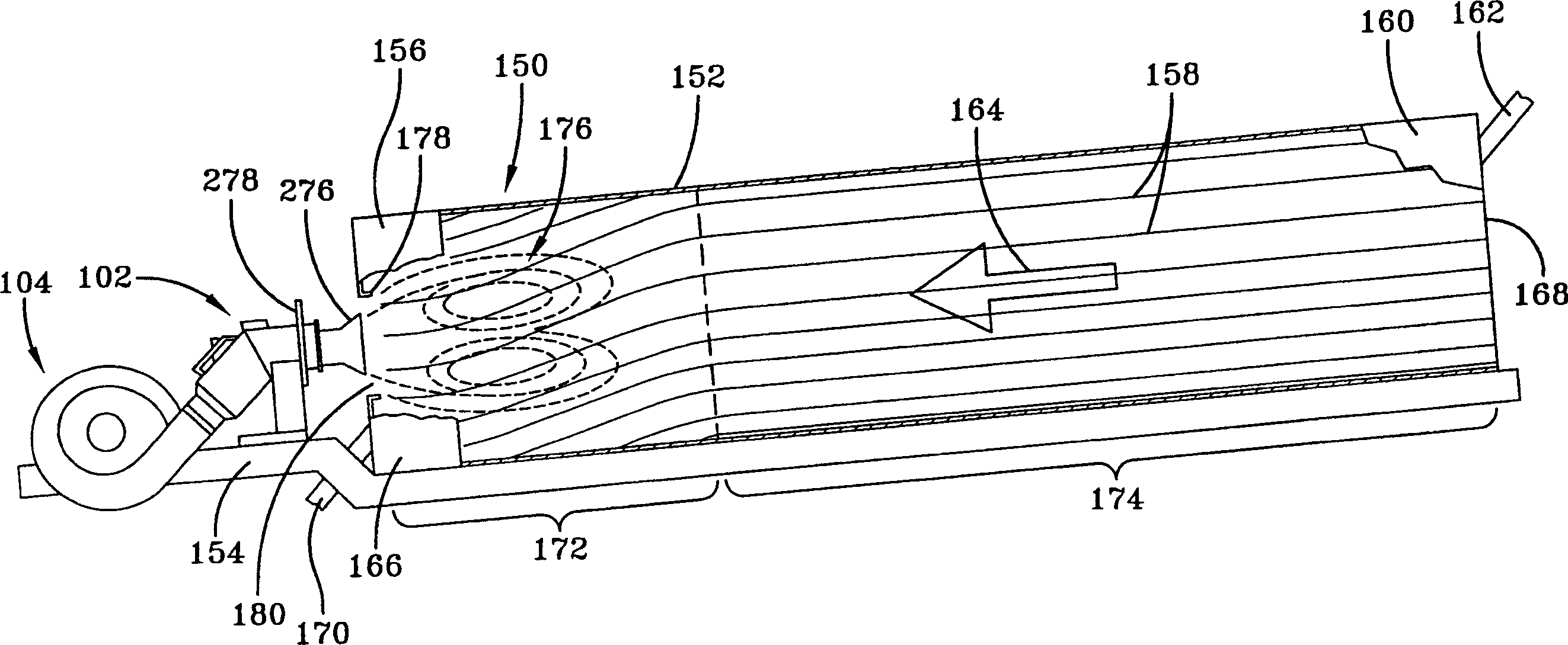
[0029] figure 2 Another portable rotary stockpile dryer, countercurrent dryer 150, for drying and preheating stockpile mixed with petroleum-based materials in the manufacture of paving asphalt, is schematically shown, heated...


PUM


Abstract

A swirl-type internal flame recirculation burner apparatus and method as used to fire asphalt plant aggregate dryers, air heaters and calcining kilns and method includes a compressed air oil atomizer assembly. The burning and swirling fuel and primary main combustion air mixture recirculates upstream along the burner axis. The secondary main combustion air may be swirled. The burner may also be fired on gas or a combination of gas and oil.

Description

technical field [0001] The present invention relates generally to burners for drying push stock in rotary dryers and rotary dryer systems, and in particular to burners for asphalt laying. Background technique [0002] A conventional heap dryer burner known in the art is disclosed in US Patent No. 4,559,009 issued December 17, 1985 to Hauck Manufacturing Co. of Lebanon, PA, and incorporated herein by reference. This prior art burner uses a low pressure air oil atomizer relying solely on the main burner air blower to generate the pressure required to atomize the fuel oil. [0003] While this prior art burner generally works well, there are 50 hertz air blowers in many parts of the world that produce air with a pressure of 24 osig (ounces per square inch). A 50 Hz blower supplying air at 24 osig pressure will work well with conventional stock drying burners using light oil, but 24 osig air will not burn heavy oil efficiently. To achieve the higher burner discharge pressures o...

Claims


Application Information

Patent Timeline
Patent Type & Authority Applications(China)
IPC IPC(8): F23C7/00F23D11/10F26B11/02
CPCF26B11/028F23D11/107F23C7/006
Inventor 约翰·A·马里诺詹姆斯·J·菲斯雷蒙德·F·鲍姆
Owner HAUKE MFG
Why Eureka
Try Eureka