
Surface processing apparatus

A technology for surface treatment devices and treatment chambers, which is applied in the direction of irradiation devices, exposure devices for photolithography, electrical components, etc., can solve problems such as the complexity of the structure of surface treatment devices, and achieve the effects of improving surface treatment efficiency and simplifying structures

Inactive Publication Date: 2004-12-01
TOKYO ELECTRON LTD
View PDF1 Cites 2 Cited by
  • Summary
  • Abstract
  • Description
  • Claims
  • Application Information

AI Technical Summary

Problems solved by technology

[0012] However, in the method of providing an intermediate electrode for applying a predetermined DC voltage between the above-mentioned EB tube and the mounting table, a power supply for applying a DC voltage; and wiring for connecting the above-mentioned power supply and the intermediate electrode inside the processing chamber are required. Inside the treatment chamber, in order to prevent abnormal discharge from occurring in the above-mentioned wiring, it is necessary to take insulation measures, so the structure of the surface treatment device will be complicated

Method used


Image

  • Surface processing apparatus
  • Surface processing apparatus
  • Surface processing apparatus

Examples


Embodiment Construction

[0052] Next, an object surface treatment device according to a first embodiment of the present invention will be described with reference to the drawings.

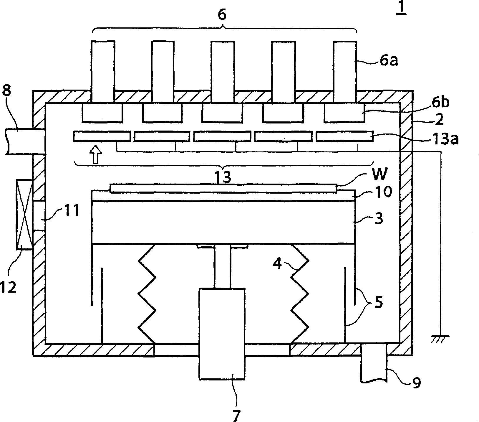
[0053] figure 1 A schematic configuration diagram showing a surface treatment device according to a first embodiment of the present invention. This surface treatment apparatus irradiates electron beams to a semiconductor wafer W or the like as an object to be processed, and performs curing treatment (surface treatment) to improve the mechanical strength of the resist.

[0054] exist figure 1 Among them, the surface treatment device 1 includes: a material such as aluminum, etc., whose interior is constituted as a cylindrical vacuum chamber 2 (processing chamber) that can be airtightly closed; disposed inside the vacuum chamber 2, and the semiconductor wafer W The surface to be processed faces the mounting table 3 on which the semiconductor wafer W is placed substantially horizontally at the top of the figure; it is plac...


PUM


Abstract

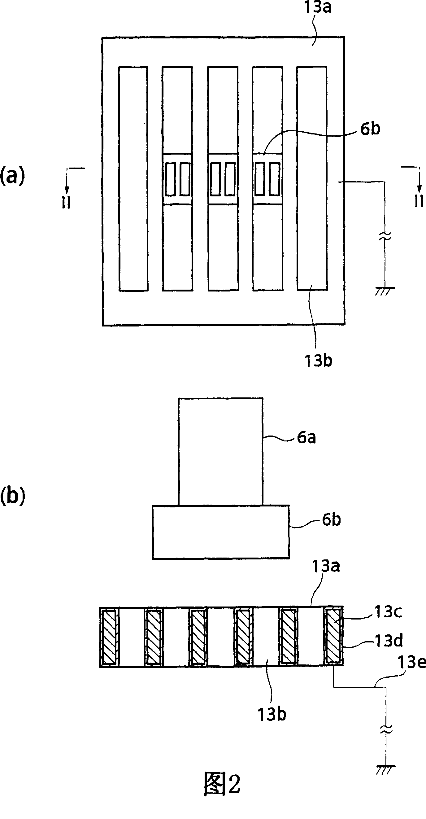
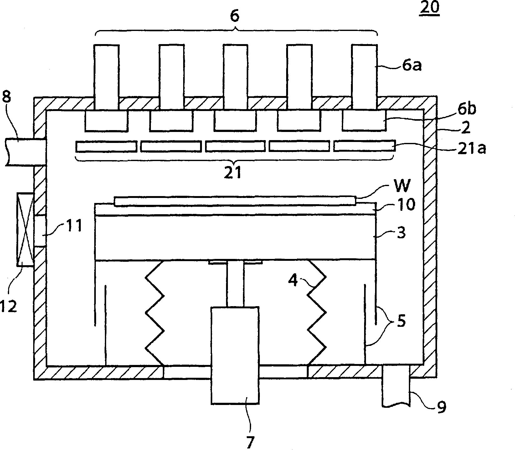
Provided is a surface treatment apparatus which can reduce the energy of an electron beam and simplify a constitution. The surface treatment apparatus 1 is equipped with a mounting stand 3 for mounting almost horizontally a semiconductor wafer W in a vacuum chamber 2, an electron beam irradiation mechanism 6 which is arranged at a ceiling of the vacuum chamber 2 and irradiates the semiconductor wafer W with an electron beam, and a self-field generator 13 arranged between the mounting stand 3 and the electron beam irradiation mechanism 6. The self-field generator 13 is constituted of a plurality of electro static charge boards 13a which are arranged in face to face with each of irradiation windows 6b in the electron beam irradiation mechanism 6. The electro static charge board 13a is a plate-like object, has five slits 13b which passes the electron beam on the facing surface which faces the irradiation windows 6b, and is provided with an internal component 13c constituted of a conductor, an external component 13d constituted of an insulator covering the internal component 13c, and a wire 13e which grounds the internal component 13c.

Description

technical field [0001] The present invention relates to a surface treatment device for modifying a resist and an insulating film by irradiating electron beams to a target object such as a semiconductor wafer or a glass substrate in a vacuum environment. Background technique [0002] Conventionally, in the field of manufacturing semiconductor devices, after a lithography process of transferring a circuit pattern onto a semiconductor wafer W using a resist, a curing process of hardening the resist and increasing the mechanical strength of the resist is performed. When this curing treatment is performed, the resist is hardened by modifying the resist by electron beam (EB) irradiation. [0003] Figure 4 It is an explanatory diagram of an electron beam irradiation device (surface treatment device) used in conventional curing treatment. [0004] exist Figure 4 Among them, the electron beam irradiation device 50 includes: a processing chamber 51 for curing the semiconductor wafe...

Claims


Application Information

Patent Timeline
Patent Type & Authority Applications(China)
IPC IPC(8): G21K5/04G03F7/20G03F7/40H01J37/30H01J37/317H01L21/027H01L21/31
CPCH01J2237/3156H01J37/317
Inventor 本多稔野中龙光冈一行
Owner TOKYO ELECTRON LTD
Learn More