Composite material vacuum auxiliary forming process

A vacuum-assisted molding technology, applied to improve the internal and surface quality of vacuum-assisted molding products, the field of vacuum-assisted molding technology, can solve problems affecting product quality stability, molding failure, resin short circuit, etc., to achieve process stability and The effect of improving and improving the inherent quality of products, saving manufacturing costs, and improving reliability

Active Publication Date: 2004-12-15
NO 53 RES INST OF CHINA NORTH IND GRP
View PDF2 Cites 35 Cited by
  • Summary
  • Abstract
  • Description
  • Claims
  • Application Information

AI Technical Summary

Problems solved by technology

[0007] The process methods disclosed in the above two patents have a certain effect on reducing the internal and surface defects of the molded products and improving the molding quality, but they do not overcome the difficulties caused by the difficulty in controlling the flow state of the resin when the above-mentioned molding process is used to form composite products. Resin short circuit phenomenon
Resin short circuit is easy to cause air bubbles to be trapped in the composite material prefabricated parts, resulting in quality defects such as pores and dry spots, which affects the stability of product quality, and even leads to molding failure in serious cases, and the reliability of the process is not high

Method used


Image

  • Composite material vacuum auxiliary forming process
  • Composite material vacuum auxiliary forming process
  • Composite material vacuum auxiliary forming process

Examples


Embodiment 1

[0028] Prepare a glass fiber reinforced composite plate with a size of 400mm×300mm×10mm

[0029] Raw materials: prefabricated parts: made of glass fiber fabric with an area density of 400;

[0030] Resin system: 196 # 100 parts of polyester resin; 1 part of methyl ethyl ketone peroxide; 1 part of cobalt naphthenate;

[0031] Release cloth 3: use 0.1mm thick polytetrafluoroethylene glass fiber cloth;

[0032] Release cloth 5: polyester film with a thickness of 0.08 mm;

[0033] Mesh resin diversion medium 13: 40-mesh woven mesh cloth is used;

[0034] Exhaust channel 10: use 60-mesh woven mesh cloth;

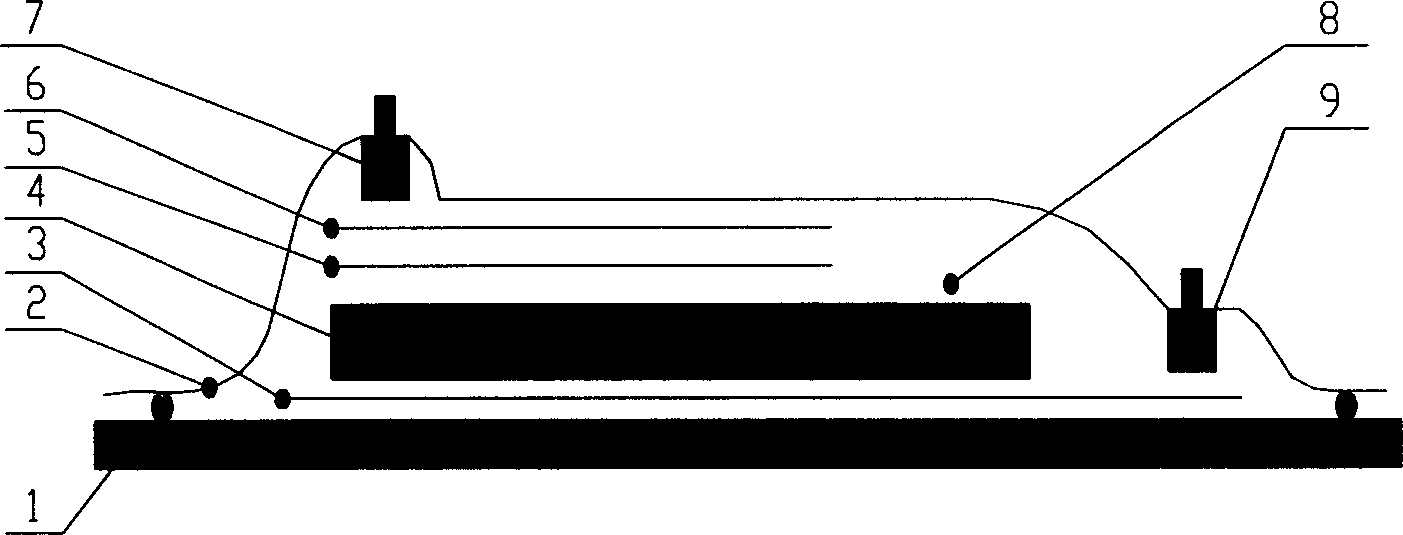
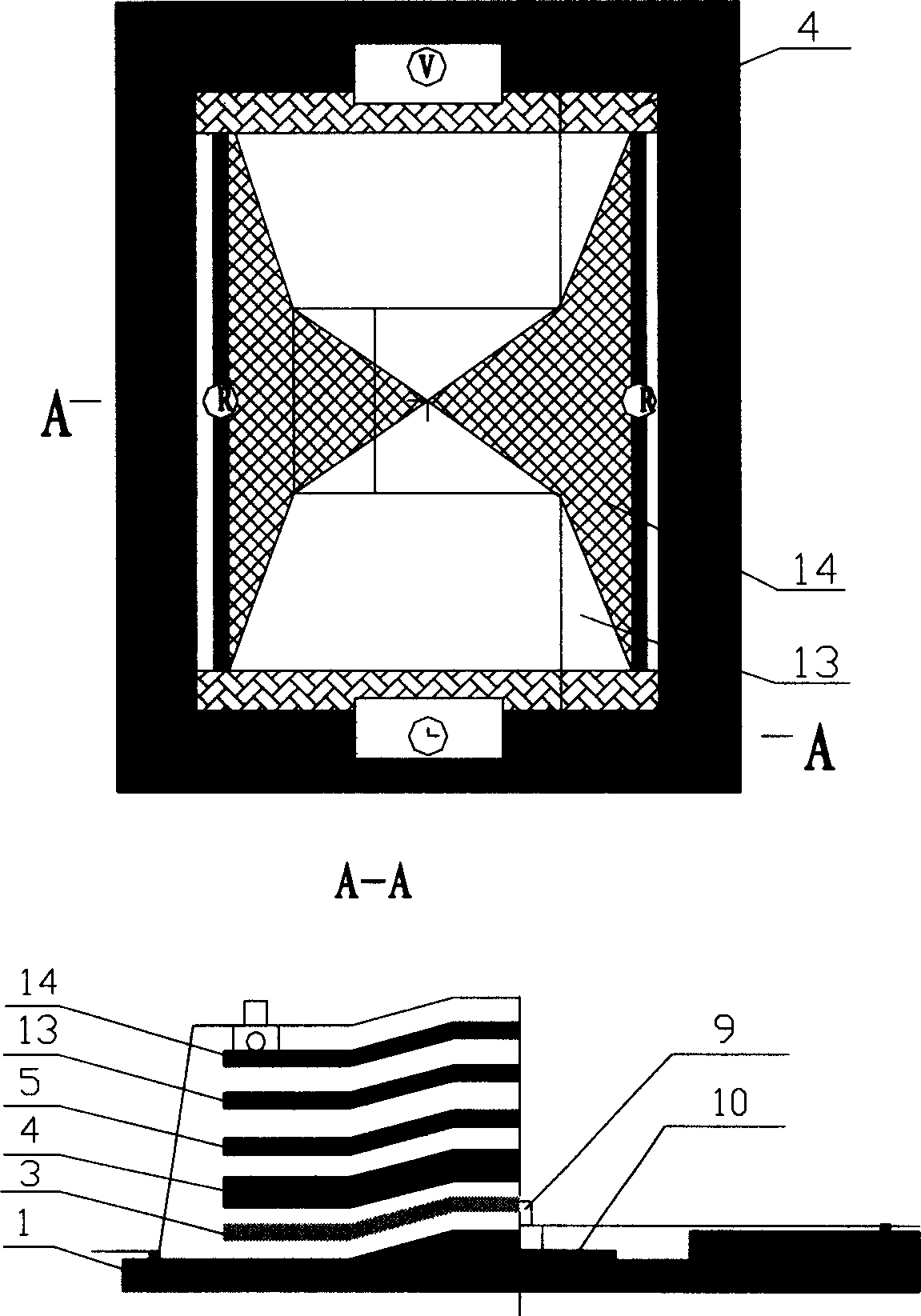
[0035] Forming process: the laying structure of each layer is shown in Figure 5. Cut the fiber-reinforced fabric into several cloth pieces of 420mm×310mm to make prefabricated part 4, prepare 3 pieces of release cloth of 420mm×310mm, one piece of release cloth 5 of 400mm×300mm and one piece of mesh resin diversion medium 13, each of 300m...

Embodiment 2

[0038] Prepare a glass fiber reinforced composite plate with a size of 4000mm×2000mm×25mm

[0039] Raw material used is with embodiment one.

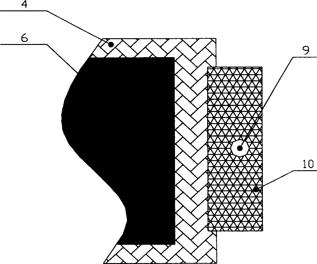
[0040] Forming process: The laying structure of each layer during the forming process is shown in Figure 6. Cut the fiber reinforced fabric into several cloth pieces of 4100mm×2100mm to make prefabricated part 4, prepare 3 pieces of release cloth of 4100mm×2100mm, one piece of release cloth 5 of 4000mm×2100mm and one piece of mesh resin flow guide medium 13, the shape The dimensions are bottom×height=4000mm×1050mm triangular mesh resin diversion medium 14 two pieces, 500mm×200mm exhaust channel 10 two pieces.

[0041] On the plane formwork 1, lay the release cloth 3 and the prefabricated part 4 in sequence, lay the release cloth 5 and the lower layer of resin diversion medium 13 in the center on the prefabricated part 4 in sequence, and in the area of ​​the lower layer of resin diversion medium, the top Lay the triangular upper layer ...


PUM

PropertyMeasurementUnit
widthaaaaaaaaaa

Abstract

The present invention relates to the basic technological process the same as traditional vacuum auxiliary forming process. The present invention has the obvious features that resin baffling area is set in the edges of prefabricated part to lower the resin flow rate and form perfect soaking of resin to the prefabricated part; that air exhaust passage is set in the air exhaust system to form the 'line type' air exhaust structure for fast exhaust of air inside the vacuum bag; and that resin medium guiding laminated and spread structure is applied to control the flow state of resin effectively. The said technological process can raise the reliability and product quality of complicated product, and has low supplementary material consumption.

Description

technical field [0001] The invention belongs to the technical field of composite material molding technology, and relates to vacuum-assisted molding technology, in particular to a method for improving the internal and surface quality of vacuum-assisted molding products. Background technique [0002] The vacuum-assisted molding process is a composite material molding process that only uses vacuum negative pressure as power to achieve resin introduction, fiber impregnation, and resin curing. Using vacuum negative pressure as the driving force, the resin is sucked into the prefabricated part arranged in the vacuum bag through the preset resin flow channel, so as to realize the infiltration of the resin on the fiber, and solidify and form without additional pressure. Among the many factors affecting the quality of vacuum-assisted molding composite products, the design and mode of the resin flow control system and vacuum exhaust system have an important impact on the intrinsic qu...

Claims


Application Information

Patent Timeline
Patent Type & Authority Applications(China)
IPC IPC(8): B29C70/36B29C70/48
Inventor 郑威张锐袁秀梅高泉喜王昭亮
Owner NO 53 RES INST OF CHINA NORTH IND GRP
Why Eureka
Try Eureka