Magnetic linear piston pump

A linear piston and magnetic force technology, applied in the direction of pumps, pump components, variable capacity pump components, etc., can solve the problems of short service life and easily damaged pistons, and achieve the effects of long service life, low energy consumption and simple structure

Inactive Publication Date: 2004-12-15
俞国淼
View PDF1 Cites 25 Cited by
  • Summary
  • Abstract
  • Description
  • Claims
  • Application Information

AI Technical Summary

Problems solved by technology

The disadvantage is that the piston as the induction body is easily damaged and has a short service life.

Method used


Image

  • Magnetic linear piston pump
  • Magnetic linear piston pump
  • Magnetic linear piston pump

Examples


Embodiment Construction

[0017] The present invention will be further described below in conjunction with accompanying drawing and specific embodiment:

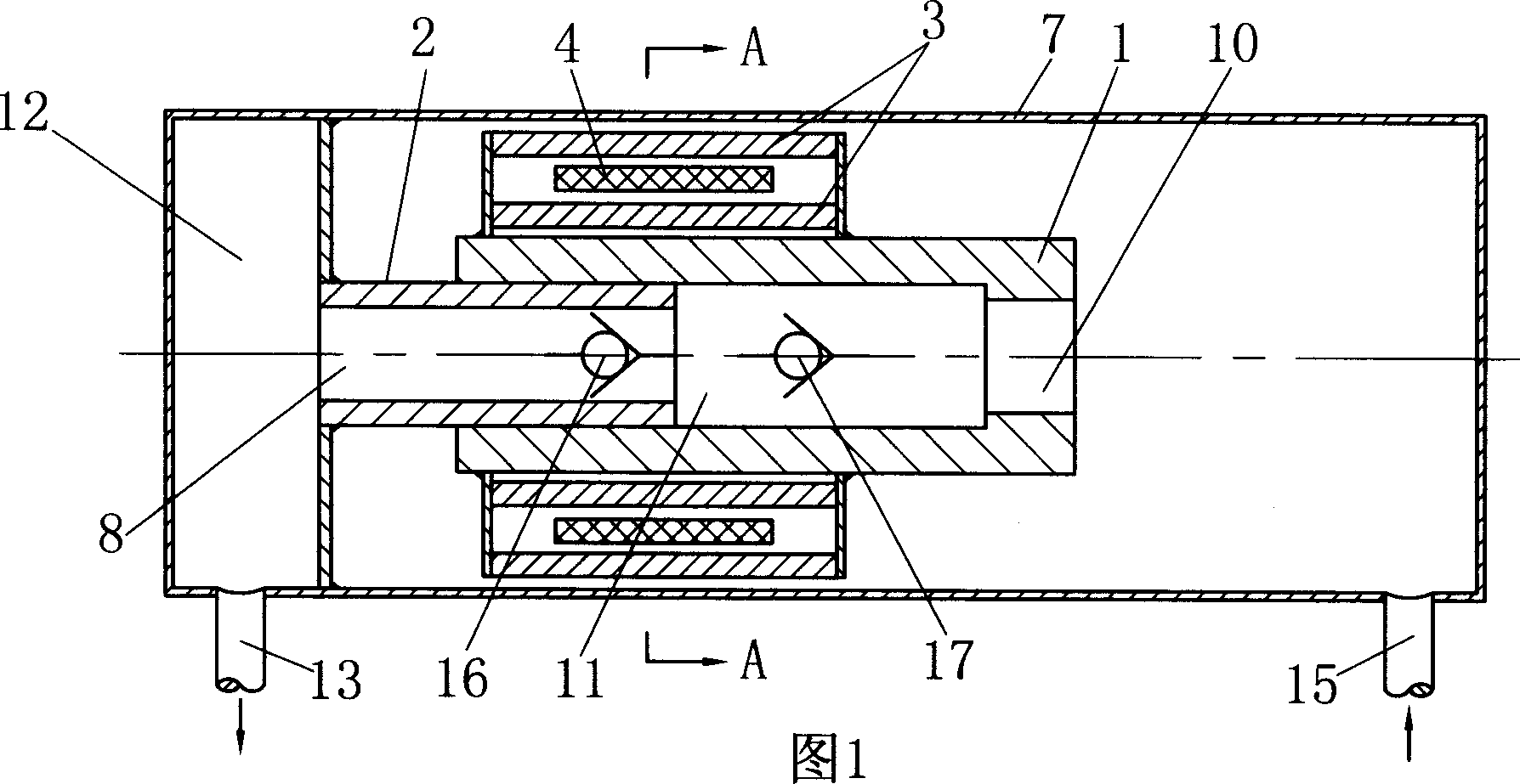
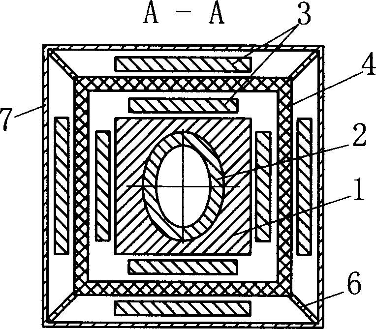
[0018] As shown in Figure 1, it is a structural sectional view of Embodiment 1, figure 2 It is a cross-sectional view of A-A in Fig. 1. The magnetic linear piston pump includes a housing 7 and a cylinder 1 and a piston 2 disposed therein. The piston 2 is disposed in the cylinder 1 for axially movable air-tight fit. The outer peripheral surface is provided with an electromagnetic coil 4, the electromagnetic coil 4 is fixed in the housing 7, the electromagnetic coil 4 is connected with the oscillating power supply, and a permanent magnet 3 is also arranged on the outer peripheral surface of the cylinder body 1, and the permanent magnet 3 is positioned and connected with the cylinder body 1 , one end of the piston 2 is fixedly connected with the housing 7, and the other end is arranged in the inner hole of the cylinder body 1, the piston 2 is provided w...


PUM


Abstract

The piston pump to utilize alternate magnetic field to produce linear motion includes casing, cylinder inside the casing, piston inside the cylinder to fit the cylinder axially and airtightly, electromagnetic coil around the cylinder and connected to vibrating power source, and permanent magnet connected to the outside of the cylinder. The piston has one end connected to the casing and the other end inside the inner hole of the cylinder and is provided with fluid hole. There are the first non-return valve and the second non-return valve set in the fluid hole or inner cylinder cavity to constitute three independent cavities, including low pressure cavity communicated with the inflow pipe, variable volume work cavity and high pressure cavity communicated with the outflow pipe. The present invention has the advantages of simple structure, low power consumption, low noise, etc. and may be used in pumping oil, water and other medium and in compressor.

Description

technical field [0001] The invention relates to a variable volume fluid pump, in particular to a piston pump which utilizes an alternating magnetic field to generate linear motion. technical background [0002] At present, there are many types of pressure pumps, such as gear pumps, vane pumps, plunger pumps, etc. in hydraulic pumps, and magnetic pumps that are mostly used for corrosive media. The mechanical movement and working principle of the magnetic force linear piston pump involved in the present invention are similar to those of the plunger pump, both use the relative reciprocating motion between the plunger (piston) and the cylinder to make the volume of the sealed working chamber in the pump change to realize the fluid flow. The effect of suction and pressure, but the reciprocating motion of the plunger pump is transformed from the rotary motion, its structure is complicated, the manufacturing cost is high, the energy consumption and noise are also large, and the mag...

Claims


Application Information

Patent Timeline
Patent Type & Authority Applications(China)
IPC IPC(8): F04B17/04F04B53/10H02K33/18
Inventor 俞国淼
Owner 俞国淼
Why Eureka
Try Eureka