Control method and control circuit of output light power and extinction ratio of light transmitter

A technology of optical transmitter and control method, which is applied in the direction of electrical components, transmission systems, electromagnetic wave transmission systems, etc., can solve the problems of injury to users, inability to solve individual differences in laser performance, low frequency response of backlight photocells, etc., and achieve extended The effect of longevity

Inactive Publication Date: 2004-12-15
HISENSE & JONHON OPTICAL ELECTRICAL TECH CO LTD
View PDF0 Cites 18 Cited by
  • Summary
  • Abstract
  • Description
  • Claims
  • Application Information

AI Technical Summary

Problems solved by technology

Since the frequency response of the backlight photocell is very low, it cannot respond to the change of the output optical power with the communication signal in real time, and can only reflect its average value, so it cannot be used to control the modulation amplitude of the transmitter light source, and it cannot be used for automatic modulation of the modulated signal. Control can only be compensated ba

Method used


Image

  • Control method and control circuit of output light power and extinction ratio of light transmitter
  • Control method and control circuit of output light power and extinction ratio of light transmitter

Examples


Embodiment 1

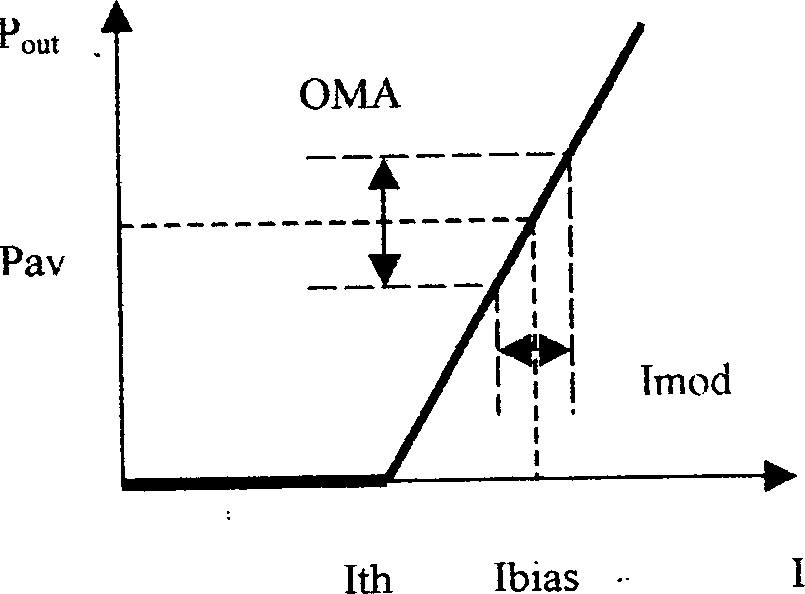
[0039] Example 1. A method for controlling output optical power and extinction ratio of an optical transmitter. It still uses the APC circuit for automatic control, monitors the change of the average luminous power through the backlight photocell, and adjusts the average output light power Pav by changing the Ibias bias current. It includes the following steps:

[0040] ①Set the average output optical power Pav, bias current Ibias, threshold Ith, and optical modulation amplitude OMA of the initial working point of the light source at room temperature 0 , Extinction ratio ER 0 And the modulation current Imod, calculate the slope SE of the curve at room temperature 0 =OMA / Imod;

[0041] ②Set the variable ranges of Pav, Ibias, Ith, OMA, ER, and Imod variables allowed by the optical transmitter to Pav±Δ 1 、Ibias±Δ 2 、Ith±Δ 3 、OMA±Δ 4 、ER±Δ 5 、Imod±Δ 6 ;

[0042] 3. Utilize the automatic optical power control circuit APC to control and keep Pav constant, and monitor Ibia...

Embodiment 2

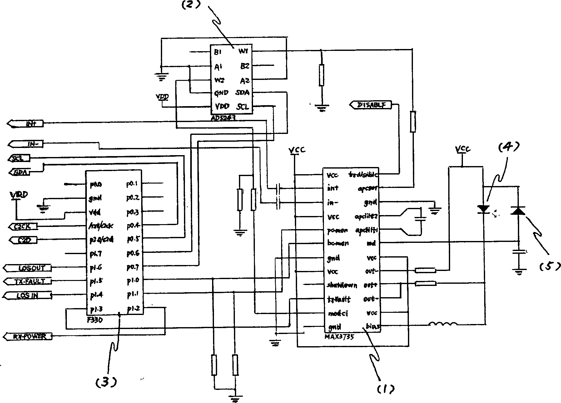
[0046] Example 2. A control circuit for output optical power and extinction ratio of an optical transmitter, as shown in FIG. 2 . It includes a driver (1), a digital potentiometer (2), a microprocessor (3), a laser (4), and a backlight photoelectric tube (5). The out-pin of the driver (1) is connected to Vcc and the positive pole of the laser (4) and the negative pole of the backlight photocell through a resistor, its bias pin is connected to the negative pole of the laser (4) through an inductance coil, and its md pin is connected to the backlight photocell ( 5) Positive connection. The driver (1), digital potentiometer (2) and microprocessor (3) are interconnected with each other.

[0047] The model of the driver (1) is MAX3735, the model of the digital potentiometer (2) is AD5243, and the model of the microprocessor (3) is F330.

[0048] Embodiment 1 and Embodiment 2 can automatically control the average output optical power and extinction ratio of the optical transmitte...


PUM


Abstract

A method and a circuit for controlling light power output and extinction ratio of a light emitting machine applies an APC circuit and back-lighted phototube monitor to alter Ibias and regulate Pav. The method includes setting an initial working point of a light source under the ordinary temperature, designing the allowed variation sphere for Pav, Ibias, Ith, OMA, ER and Imo to utilize APC to make Pav unchanged and monitor other variable quantities, when variables of temperature and time surpass the variation sphere, then other variables are regulated to restore the controlled variables to original spheres, computing Pav, I bias, Ith and SE ordinary temperature set value and regulating Imod to enable OMA and ER at the initial set value. The circuit includes a driver, a digital potentiometer, a microprocessor and a laser etc.

Description

technical field [0001] The invention belongs to the technical field of optical communication control, and more specifically relates to a method for controlling output optical power and extinction ratio of an optical communication transmitter and an improvement of an automatic control circuit thereof. Background technique [0002] At present, the luminous efficiency of various lasers and light-emitting diodes and other light sources is constantly changing with the working temperature and the aging of the light source, which will seriously affect the working stability of the optical transmitter, the reliability of communication and the communication bit error rate and other indicators. At present, the average output optical power can be automatically controlled by the APC circuit. APC uses the backlight photocell packaged with the light source to detect the output optical power, and then controls the driving bias current of the light source through the feed...

Claims


Application Information

Patent Timeline
IPC IPC(8): H04B10/564
Inventor 姜瑜斐赵世昌赵其圣
Owner HISENSE & JONHON OPTICAL ELECTRICAL TECH CO LTD
Why Eureka
Try Eureka