Adjustable optical phase shifter and phase-shift process

A phase shifter, optical technology, applied in the direction of using optical devices, instruments, diffraction gratings, etc., can solve the problems of precise calibration difficulties, influence of phase shift accuracy, etc.

Inactive Publication Date: 2005-01-05
TIANJIN UNIV
View PDF0 Cites 9 Cited by
  • Summary
  • Abstract
  • Description
  • Claims
  • Application Information

AI Technical Summary

Problems solved by technology

This method of generating optical phase shift must be calibrated before use, and accurate calibration is often very difficult
In addition,

Method used


Image

  • Adjustable optical phase shifter and phase-shift process

Examples


Embodiment Construction

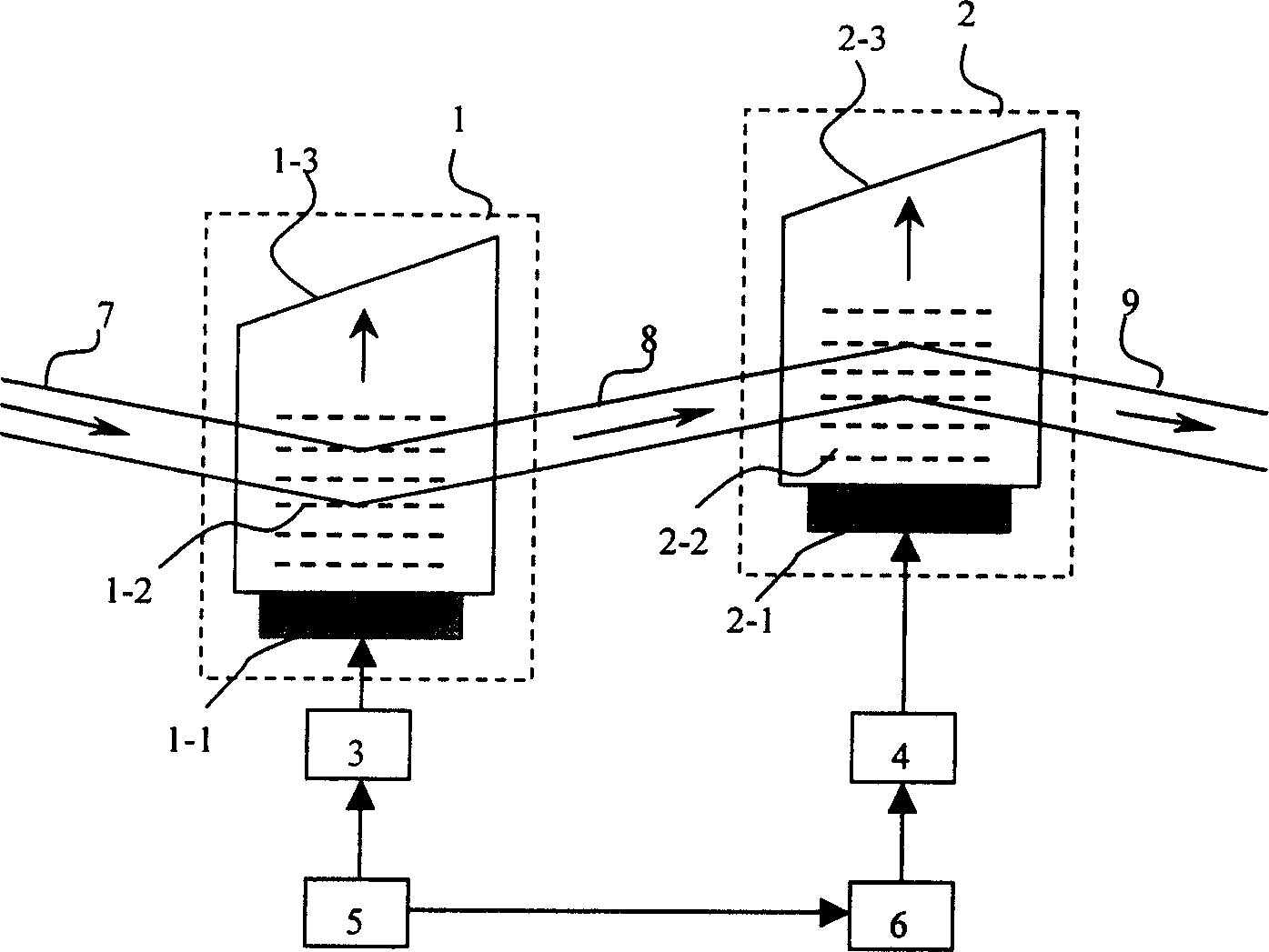
[0008] The specific implementation manners of the present invention will be described in detail below in conjunction with the accompanying drawings. as attached figure 1 As shown, the incident light beam 7 enters the acousto-optic crystal 1-3 along the direction indicated by the arrow. The incident light beam 7 interacts with the acoustic wave field 1-2 propagating in the acousto-optic crystal 1-3 along the direction indicated by the arrow, and generates first-order diffracted light 8 with positive frequency shift propagating along the direction indicated by the arrow. The acousto-optic crystal 1-3 is connected to the ultrasonic transducer 1-1, and the ultrasonic transducer 1-1 is driven by the sine wave signal output by the sine wave signal generator 5 via the signal generated by the radio frequency power amplifier 3. The light beam 8 enters the acousto-optic crystal 2-3, interacts with the acoustic wave field 2-2 propagating in the acousto-optic crystal 2-3 along the direct...


PUM


Abstract

The invention discloses an adjustable optical phase shifter and the phase shifting process, which is made up of two acousto-optic modulators, radio frequency power amplifier and sine signal generator, the output end wire of the generator, one wire is connected to the input end of the radio frequency power amplifier, another wire is connected to the a electron phase shifter in series and then connected to the input end of another radio frequency power amplifier. The phase shifting process, the incoming ray enters the acousto-optic modulator 1, the sine wave signal generator transmits radio frequency signal with the same frequency to the radio frequency power amplifier and the electro phase shifter, adjusts and controls the electron phase shifter, the two acousto-optic modulators are driven by the radio frequency signal with the same frequency and different phase; the acousto-optic modulator generates the first grade diffraction as the incoming ray of the acousto-optic modulator the diffraction of the modulator is used as the output light, the output light has the same frequency to the incoming ray and the phase can be shifted. The merits of the invention are: it needs no phase shift label, and it can generate dynamic adjustable optical phase shift.

Description

technical field [0001] The invention relates to an optical phase shifter and a phase shifting process, in particular to an adjustable optical phase shifter and a phase shifting process directly controlled by an electronic method, and belongs to the field of photoelectric measurement technology. Background technique [0002] Various precision measurement technologies based on optical interference have been widely used in many scientific research and engineering fields, including surface quality inspection of optical parts, shape measurement of three-dimensional objects, etc. In traditional interferometry, the shape and maximum error of the measured surface are generally judged by visual inspection based on the shape and position of the interference fringes. This method not only has low precision and slow speed, but also can only obtain part of the information of the measured surface. With the rapid development of photoelectric and laser technolog...

Claims


Application Information

Patent Timeline
IPC IPC(8): G01B11/00G01B11/30G02B5/18
Inventor 李恩邦姚建铨习江涛奇卡罗
Owner TIANJIN UNIV
Why Eureka
Try Eureka