Non-contact infrared thermometer and its distance control method
An infrared thermometer, non-contact technology, applied in the field of temperature measurement, can solve the problems of complex structure of the thermometer, difficult promotion and application, many additional components, etc., and achieves the effect of easy industrialized mass production, easy promotion and application, and low cost.
- Summary
- Abstract
- Description
- Claims
- Application Information
AI Technical Summary
Problems solved by technology
Method used
Image

Examples
Embodiment approach 1
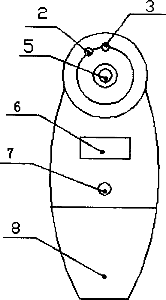
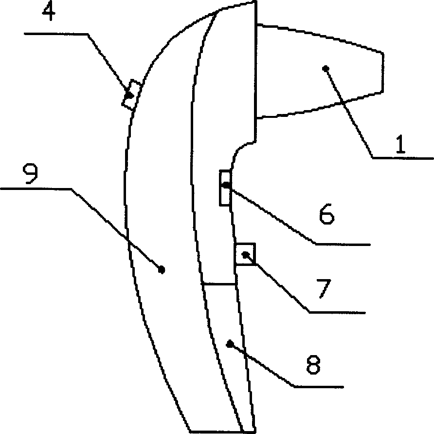
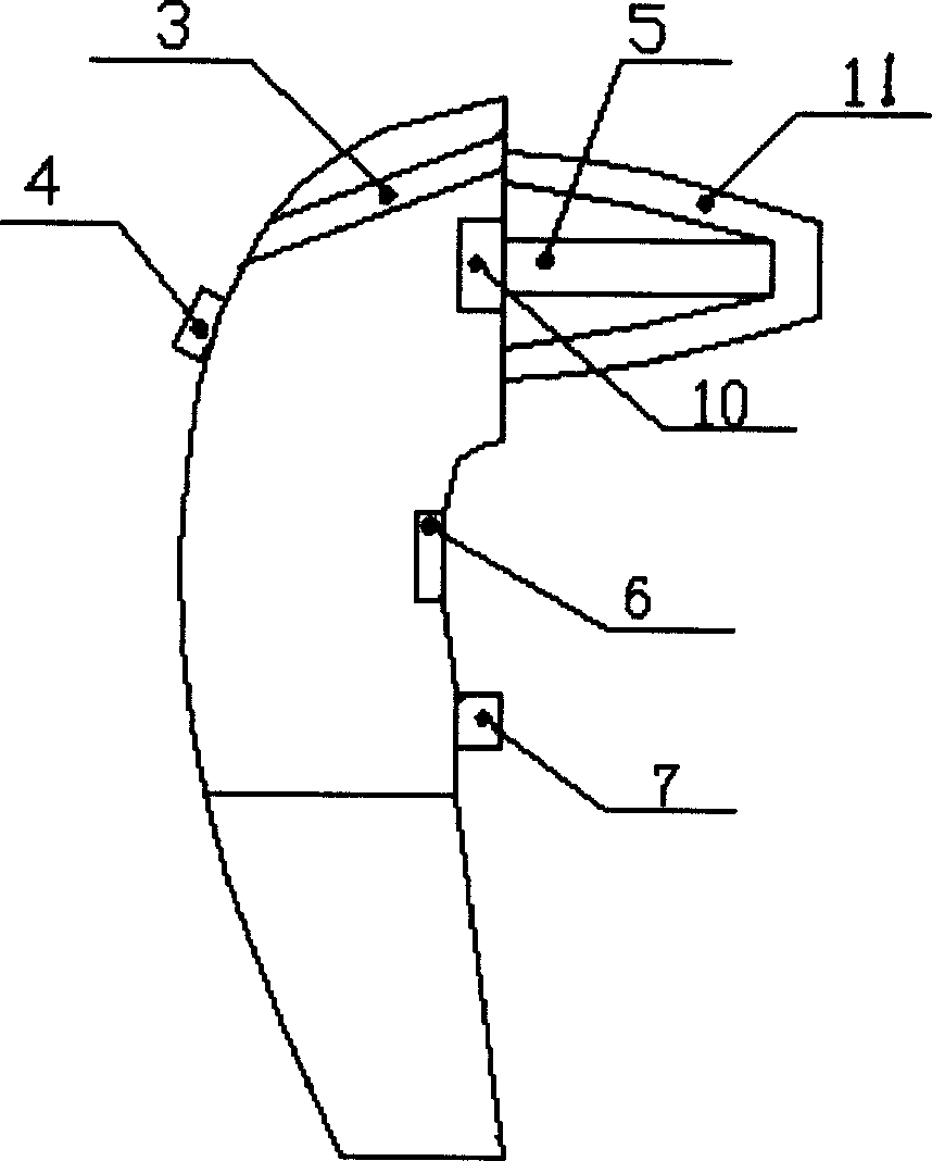
[0023] Such as Figure 1~4 As shown, a non-contact infrared thermometer and its fixed-distance control method, the thermometer mainly includes an infrared radiation sensor 10, a fixed-distance control device, a processing unit, and a display device. Its fixed-distance control device mainly includes a light-emitting mechanism 2 and an observation mechanism 3, etc., and its display device mainly includes a display circuit and a liquid crystal display 6, etc. The housing 9 of this embodiment is a hand-held type with a protruding head and a slender lower end. The protruding probe 11 is conical. The infrared sensor 10 and the fixed distance control device are installed in the probe 11. The processing unit and the display circuit are installed Set in the casing 9, the liquid crystal display 6 is installed on the surface of the casing 9, on the casing 9, a power switch / measurement key 7 and a battery cover 8 are also arranged, and the battery is installed in the casing inside the bat...
Embodiment approach 2
[0025] Such as Figure 5 As shown, the main feature of the non-contact infrared thermometer and its fixed-distance control method is that the observation mechanism of the fixed-distance control device adopts a bent tube type and an optical element (such as a mirror) is added therein to change the observation of the observation mechanism. The optical path makes the optical path of the light beam emitted by the light-emitting mechanism intersect with the observation optical path of the bent tube observation mechanism in the specific area between C and B near the preset distance L in front of the probe 11, thereby realizing the distance control. The rest is the same as Embodiment 1.
Embodiment approach 3
[0027] Such as Figure 6As shown, the main feature of the non-contact infrared thermometer and its fixed-distance control method is that the observation mechanism of the fixed-distance control device adopts an optical fiber type to change the angle and position of the observation optical path of the observation mechanism, so that the optical path of the light beam emitted by the light-emitting mechanism is consistent with the The observation optical path of the fiber-optic observation mechanism intersects in the specific area between C and B near the preset distance L in front of the probe 11, thereby realizing the fixed-distance control. The rest is the same as Embodiment 1.
PUM
 Abstract
Description
Claims
Application Information
 - R&D
- Intellectual Property
- Life Sciences
- Materials
- Tech Scout
- Unparalleled Data Quality
- Higher Quality Content
- 60% Fewer Hallucinations
Browse by: Latest US Patents, China's latest patents, Technical Efficacy Thesaurus, Application Domain, Technology Topic, Popular Technical Reports.
© 2025 PatSnap. All rights reserved.Legal|Privacy policy|Modern Slavery Act Transparency Statement|Sitemap|About US| Contact US: help@patsnap.com