High precision flexible parallel robot with six degreed of freedom and large travel

A large-stroke, high-precision technology, applied in the field of parallel high-precision position adjustment robots, can solve the problem of small movement range of the adjustment device

Inactive Publication Date: 2005-01-12
HARBIN INST OF TECH
View PDF0 Cites 27 Cited by
  • Summary
  • Abstract
  • Description
  • Claims
  • Application Information

AI Technical Summary

Problems solved by technology

Therefore, although the accuracy has been significantly improved, the following problem is: due to the limited deformation of the flexible hinge, the range of motion of the adjustment device is extremely small, usually on the order of cubic microns, which is not suitable for applications that require both high precision and high precision. Applications with a large range of motion

Method used


Image

  • High precision flexible parallel robot with six degreed of freedom and large travel
  • High precision flexible parallel robot with six degreed of freedom and large travel
  • High precision flexible parallel robot with six degreed of freedom and large travel

Examples


specific Embodiment approach 1

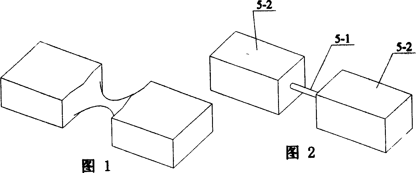
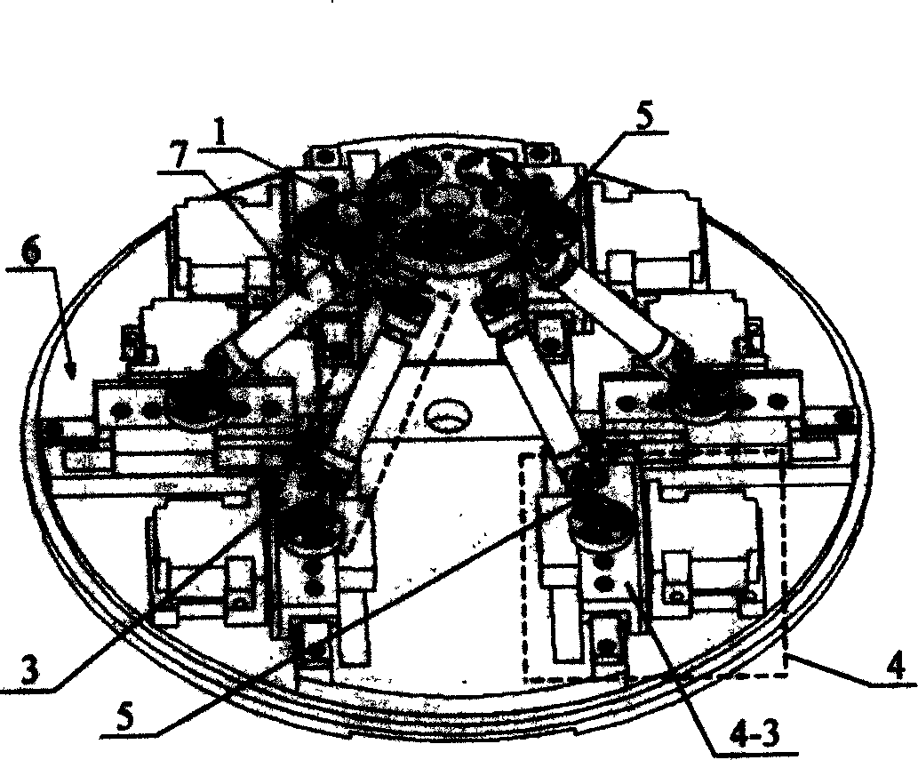
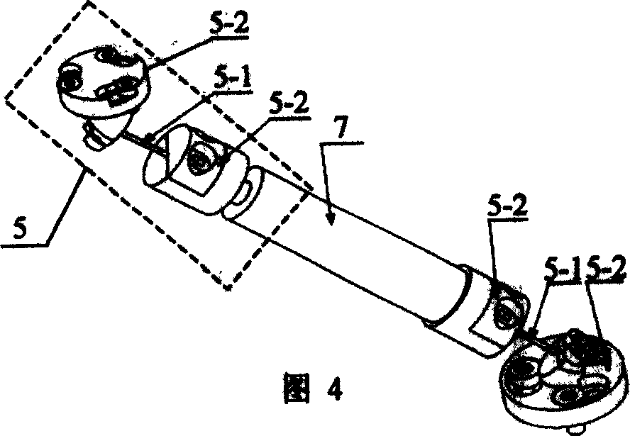
[0005] Specific implementation mode one: the following combination image 3 This embodiment will be specifically described with FIG. 4 . It consists of an upper platform 1, six sets of identical branch chains 3, six sets of identical driving devices 4 and a base 6, the branch chains 3 are evenly arranged between the upper platform 1 and the base 6, and the driving device 4 is set on the base 6, the branch chain 3 is composed of a rigid rod 7 and a large-stroke flexible hinge 5, the large-stroke flexible hinge 5 at the upper end of the branch chain 3 is connected to the upper platform 1, and the large-stroke flexible hinge 5 at the lower end of the branch chain 3 is connected to the driving device 4 Above, the large-stroke flexible hinge 5 is composed of a hinge rod 5-1 and fasteners 5-2 located at both ends of the hinge rod 5-1.

specific Embodiment approach 2

[0006] Embodiment 2: The difference between this embodiment and Embodiment 1 is that the hinge rod 5-1 is made of beryllium bronze with a diameter of 0.8-1.2 mm and a length of 10-14 mm.

specific Embodiment approach 3

[0007] Specific implementation mode three: the following combination image 3 , Figure 5 , Figure 6 and Figure 7 This embodiment will be specifically described. The difference between this embodiment and the first embodiment is that the driving device 4 consists of a piezoelectric motor 4-1, a guide rail 4-2, a slide table 4-3, a slider 4-5, a rolling body 4-6 and a friction belt 4- 4 components, the guide rail 4-2 is set on the upper surface of the base 6 in the horizontal direction, the guide rail 4-2, the slider 4-5 and the rolling element 4-6 form a linear movement pair, and the slide table 4-3 is fixedly connected to the slider On 4-5, the sliding table 4-3 is fixedly connected to the lower end of the large-stroke flexible hinge 5, and the side surface of the sliding table 4-3 is bonded with a friction belt 4-4 in the horizontal direction, and the friction finger 4 of the piezoelectric motor 4-1 -1-1 is pressed against the surface of the friction belt 4-4. The drivin...


PUM


Abstract

A 6-freedom high-precision long-stroke flexible parallel robot is composed of upper platform, base, 6 drivers on said base, and 6 branches connected between upper platform and drivers. It has submicron-class resolution and moving precision in cm-class moving range.

Description

technical field [0001] The invention relates to a parallel high-precision position adjustment robot. Background technique [0002] At present, ordinary rigid parallel position adjustment devices usually use conventional kinematic pair mechanisms such as rotating joints and moving joints, which inevitably introduce errors such as gaps and crawling in driving and passive joints, which are very difficult to control. Error sources. In order to solve the above problems, flexible hinges are usually used in existing designs to replace various conventional kinematic pairs. Most of the current flexible ball hinges are "small-stroke" flexible hinges processed by wire cutting or other processing methods, as shown in Figure 1. The characteristic is that the linear displacement is often at the micron level, and the angular displacement is below 1°. Therefore, although the accuracy has been significantly improved, the following problem is: due to the limited deformation of the flexible h...

Claims


Application Information

Patent Timeline
Patent Type & Authority Applications(China)
IPC IPC(8): B25J9/08
Inventor 孙立宁杜志江董为曲东升
Owner HARBIN INST OF TECH
Why Eureka
Try Eureka