Tool type barrel templates and tailgate platform

A tool-type, barrel mold technology, applied in the field preparation of formwork/formwork/work frame, building components, construction, etc., can solve problems such as collision with the well wall, difficult adjustment, and difficult to follow the platform in place accurately, etc. To achieve the effect of making up for high and low errors and reducing processing errors

Inactive Publication Date: 2005-01-12
马永乐
View PDF0 Cites 10 Cited by
  • Summary
  • Abstract
  • Description
  • Claims
  • Application Information

AI Technical Summary

Problems solved by technology

[0003] The purpose of the present invention is to provide a tool-type barrel form and a follow-up platform to solve the technical problem that secondary adjustment is required for the installation and removal of the well formwork, and the construction efficiency is low; to solve the slight change in the well section, the entire formwork must be reprocessed, It is not conducive to the problem of repeated use and formwork leasing; in addition, it solves the problems that the follow-up platform often collides with the well wall during the lifting process, it is difficult to leave the reserved holes for its outriggers, and the follow-up platform is not easy to accurately and easily adjust.

Method used


Image

  • Tool type barrel templates and tailgate platform
  • Tool type barrel templates and tailgate platform
  • Tool type barrel templates and tailgate platform

Examples


Embodiment 1

[0061] Embodiment 1: The present invention consists of two parts, a tool-type cylinder mold and a matching follow-up platform.

[0062] 1. Tool cylinder mold:

[0063] The tool-type barrel mold is connected as a whole by the barrel mold and the formwork support frame:

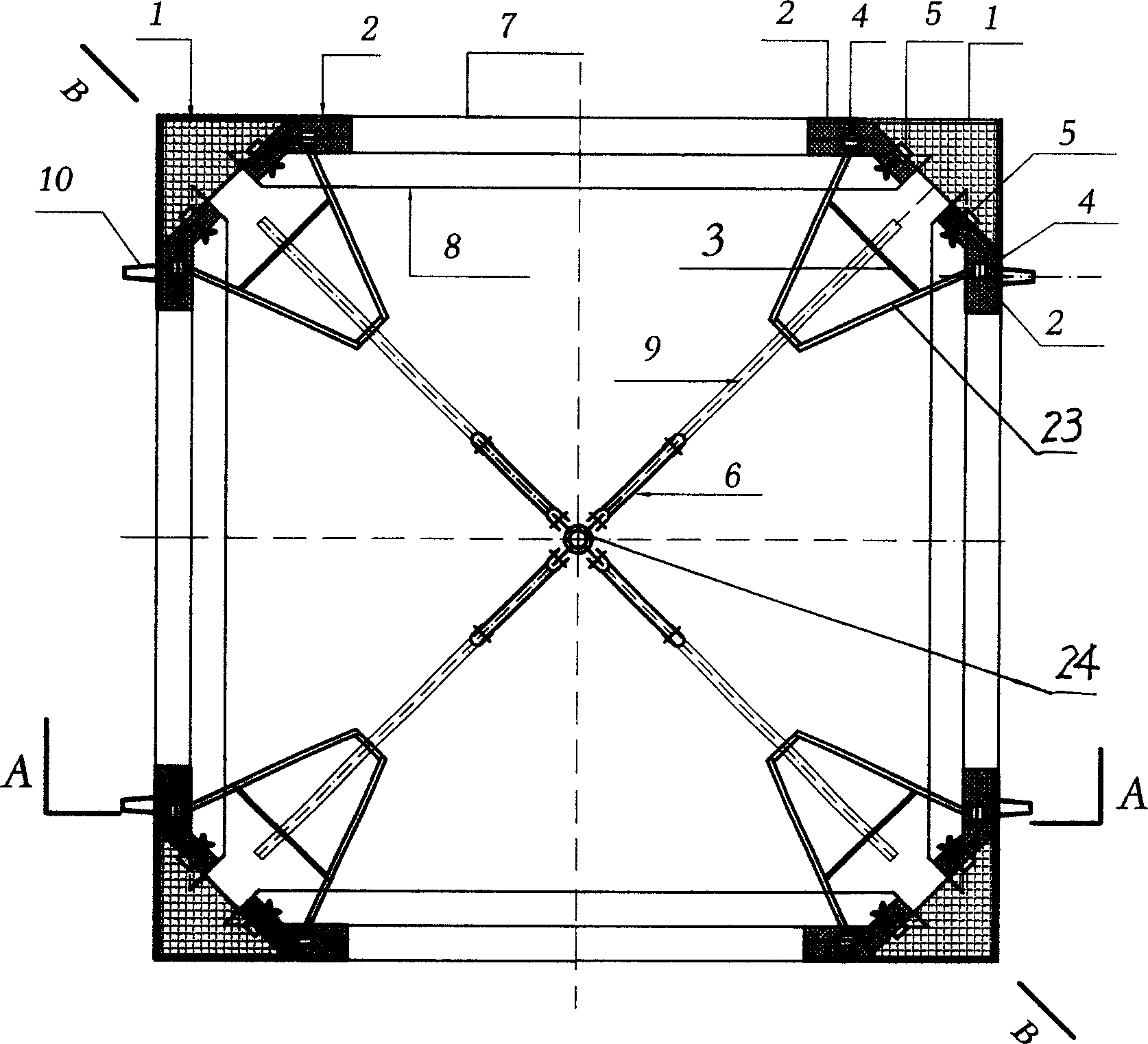
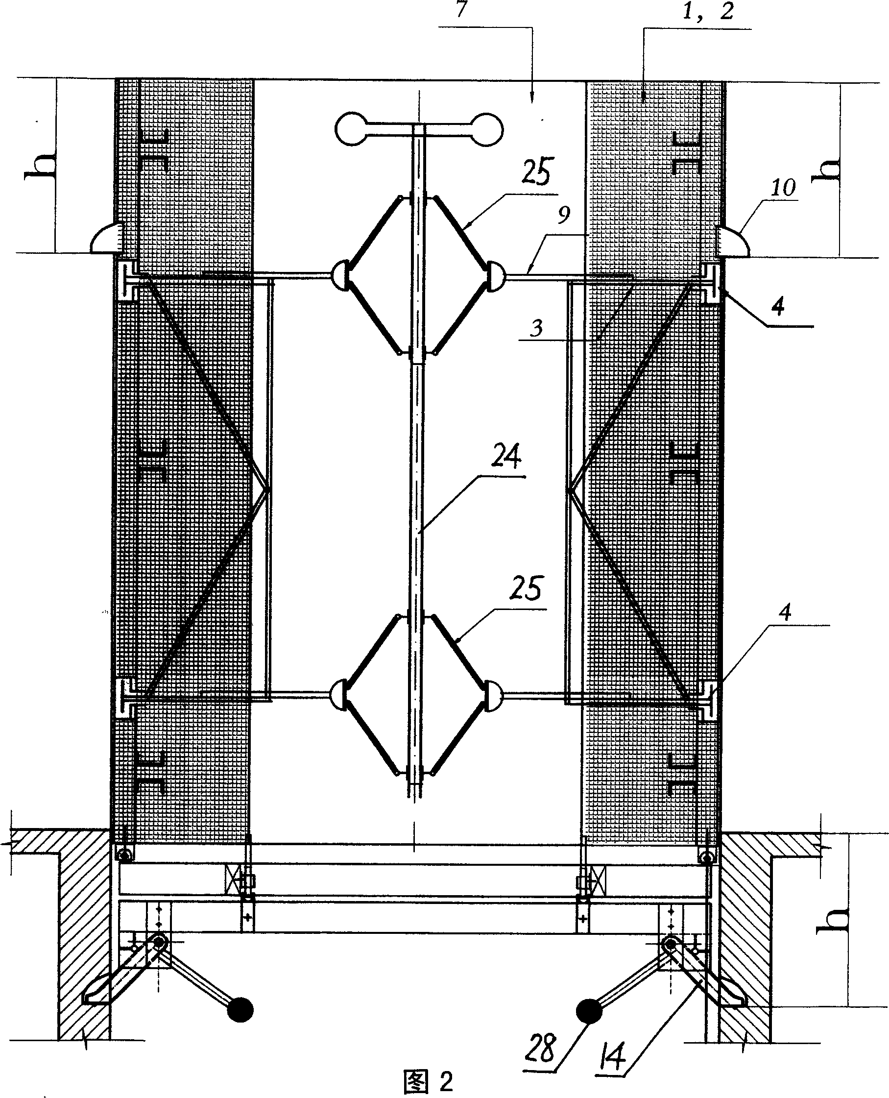
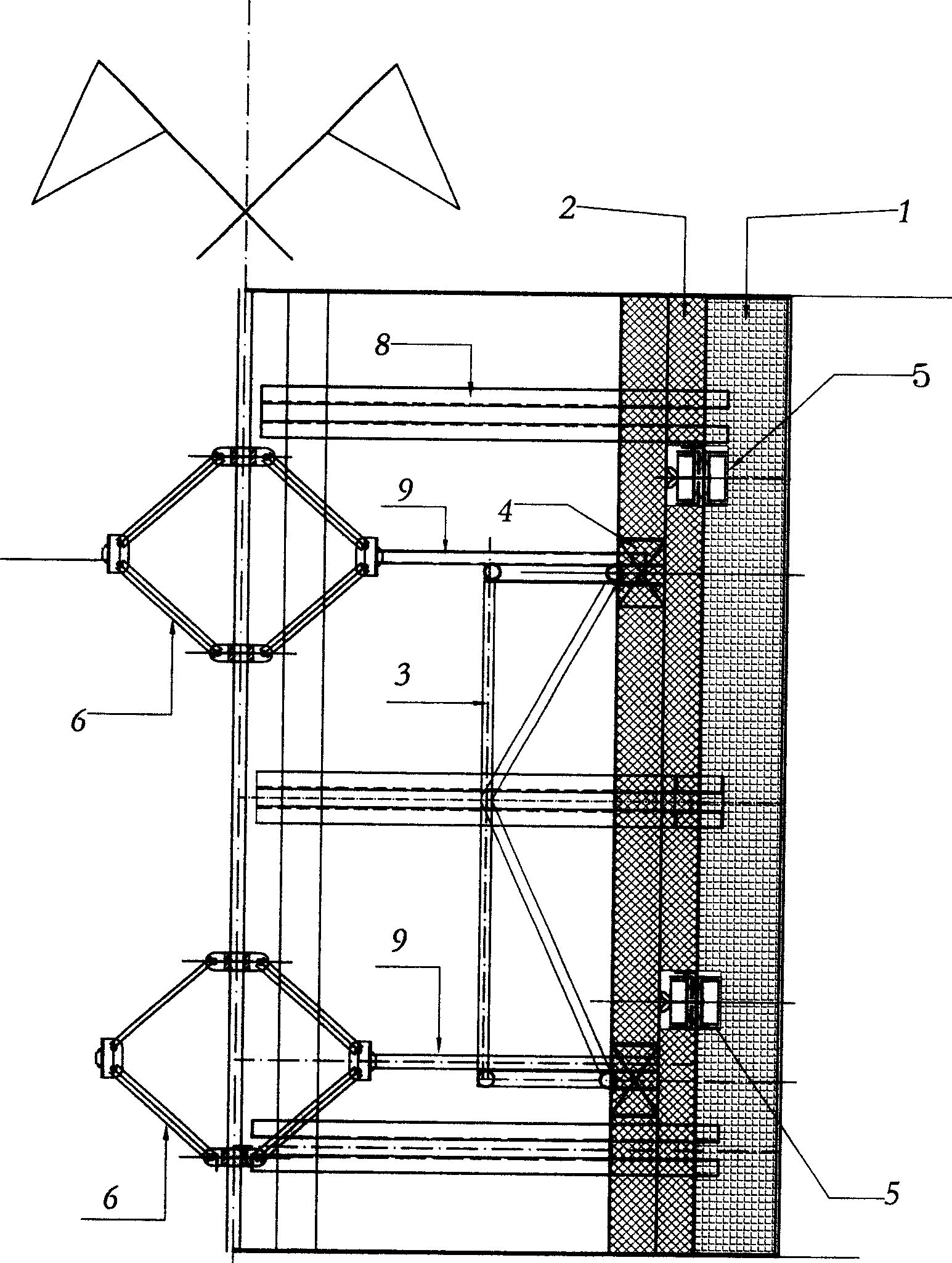
[0064] see figure 1 , 2, 3, the cylinder mold is formed by four sets of shaped corner combination mold bases and four non-stereotyped filling boards 7 drawn by back corrugated 8; Two shaped plates 2 of corner beams 5 at an angle of 135° are connected; the bottom edge of rigid corner mold 1 is connected with corner beam slider 5 in the horizontal direction, and the long side extension line of the corner beam slider is connected with the cylinder mold The diagonal line is at an angle of 45°; the formwork supporting frame is connected by a horizontal tie rod 9 with a replaceable length between the central retractable frame 6 and the force transmission frame 3, and the central retractable frame 6 and the horizont...

Embodiment 2

[0072] Embodiment 2: The force transmission frame 3 is in the shape of an isosceles triangle in the horizontal direction.

[0073] The working process of the present invention is described in detail:

[0074] 1. Tool type cylinder mold see Figure 1-13 :

[0075] The whole cylinder is composed of two major parts, the stereotyped assembly and the non-stereotyped part.

[0076] Shaped combination: It is composed of two combined units, one is the corner combined unit, including the following components: rigid corner mold 1, shaped plate 2, force transmission frame 3, shaped plate slider 4, corner beam slider 5, platform support There are six kinds of shaped parts altogether in the overturning mold box 10 in the reserved hole of the legs;

[0077] Unshaped parts include: filling board 7, back corrugated 8, horizontal tie rod 9 and other three parts. Unshaped parts are determined by the size of the shaft section.

[0078] see Figure 5 , The retractable function of the barrel...


PUM


Abstract

This is a tool-pattern cylinder model and follow-up platform. It contains: The peripheral side of cylinder model is composed with four group finalized complex model frames and four non-finalized filled plates. Every group complex model frame is formed with finalized rigid angle model and two finalized plates separately. The bottom edges of rigid angle model are horizontal and slide-able connected with the corner beam block; the finalized plate with corner beam is connected with transporting beam by finalized slide block: the central moving frame is connected with transporting beam by horizontal pull rod, to realize the draw-in and draw-out function of cylinder model; the four corners of follow-up platform have direct-able wheels, to make the platform keep proper condition during its primitive procession.

Description

technical field [0001] The invention relates to a building construction formwork, in particular to a well formwork and a matching follow-up platform. Background technique [0002] The existing shaft formwork is divided into plate structure, and there are two types: hinged well formwork and rigid angle well formwork; according to the principle of retraction and retraction, there are two types of retractable and retractable central joystick bevel gears. kind. Due to structural defects and inconvenience in use, the hinge shaft formwork is gradually being replaced by the rigid angle well formwork. But existing rigid corner shaft formwork still has many defects: main performance is: 1, the four wallboards of shaft formwork are connected and fixed by the central control rod, and then shaped by the rigid angle formwork. Before the rigid angle formwork was installed, the spatial positions of the four wall forms were not actually finalized. From the force analysis of the structura...

Claims


Application Information

Patent Timeline
Patent Type & Authority Applications(China)
IPC IPC(8): E04G11/28E04G15/00
Inventor 马永乐
Owner 马永乐
Why Eureka
Try Eureka