Chirp pulse compressor

A chirped pulse and compressor technology, applied in the field of optical pulse compressors, can solve the problems of influence, low pulse contrast, and the inability of pulse compressors to independently and completely compensate for chromatic dispersion.

Inactive Publication Date: 2005-01-12
SHANGHAI INST OF OPTICS & FINE MECHANICS CHINESE ACAD OF SCI
View PDF0 Cites 14 Cited by
  • Summary
  • Abstract
  • Description
  • Claims
  • Application Information

AI Technical Summary

Problems solved by technology

[0010] 1. This kind of grating-to-pulse compressor cannot completely and cleanly compensate the third-order and fourth-order dispersion imposed by the stretcher, laser amplification system, and other optical devices on the chirped pulse. Compensated third and fourth order dispersion
In this way, the pulse contrast after stretching, amplification and compression is low, and its contrast is generally 10 2 ~10 5 between, which seriously affects the experimental results, and limits the intensity contrast ratio of ultrashort pulses to be greater than 10 6 The use of plasma experiments in
[0011] 2. Due to the mutual influence of each order of dispersion imposed by the grating on the compressor on the optical pulse, that is to say, while adjusting the vertical distance between the two gratings in the grating pair to compensate for the second order dispersion, it also changes the third order and fourth order etc. Higher-order dispersion; changing the pulse incidence angle to compensate for third-order dispersion also affects second- and fourth-order dispersion
In this way, this kind of pulse compressor cannot completely compensate the dispersion of each order independently, and the optical pulse compressed by this kind of pulse compressor cannot have a high intensity contrast
[0012] 3. Since the pulse only experiences once in the grating pair compressor and the finite size of the grating, only one wavelength component can be completely captured by the second grating, and dispersion causes all other wavelength components to be partially lost on the second grating, which means The loss of pulse energy and the incompleteness of the spectrum will make the final pulse broaden to a certain extent (~15%)
So the traditional grating pair will reduce the focus strength and contrast of the compressed pulse

Method used


Image

  • Chirp pulse compressor
  • Chirp pulse compressor
  • Chirp pulse compressor

Examples


Embodiment Construction

[0034] The present invention will be further described below in conjunction with specific embodiments and accompanying drawings, but the protection scope of the present invention should not be limited thereby.

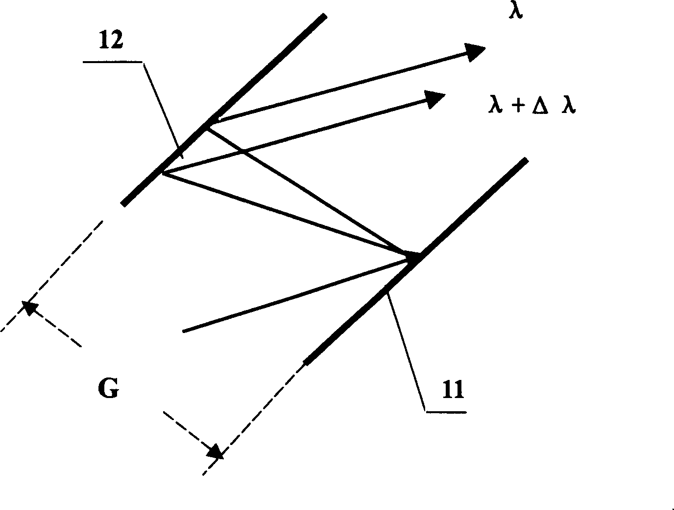
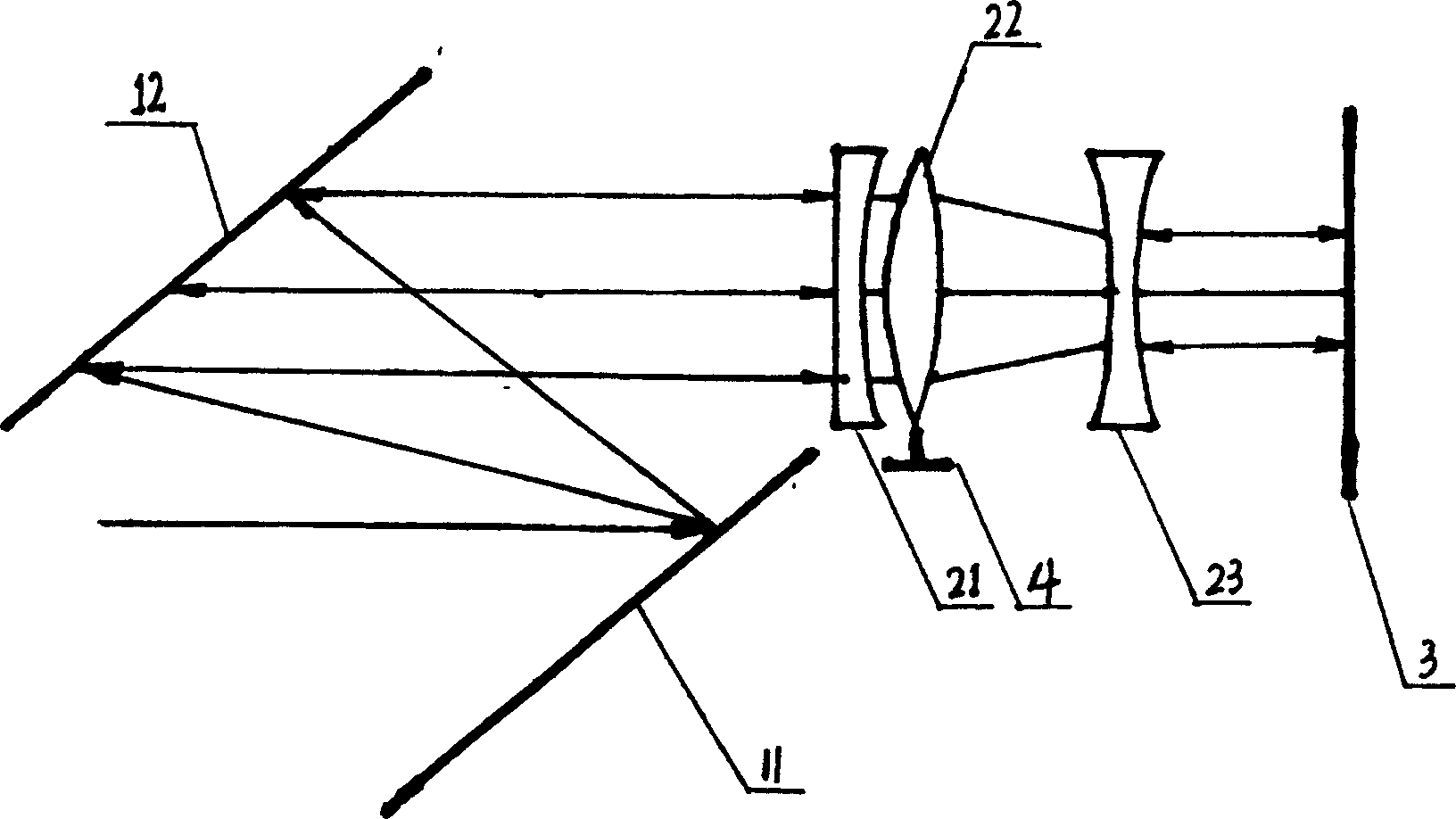
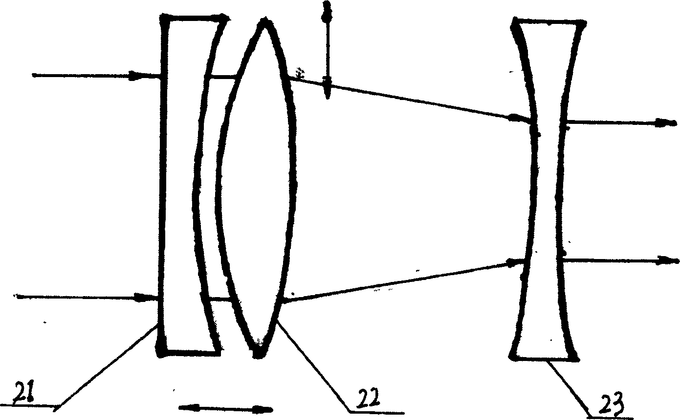
[0035] see first figure 2 , figure 2 It is a structural schematic diagram of the chirped pulse compressor of the present invention, as can be seen from the figure, the chirped pulse compressor of the present invention includes a grating pair 1 parallel to each other, and is characterized in that there are also a telescope system 2 and a total reflection mirror behind the grating pair 1 3. The telescope system 2 is sequentially composed of a plano-concave lens 21, a biconvex lens 22 and a biconcave lens 23; the rotation axes of the plano-concave lens 21 and the biconcave lens 23 are on the rotation axis of the telescope system 2, and the outgoing beam of the grating pair 1 is perpendicular to The plane of the plano-concave lens 21 of the telescope system 2, the magni...


PUM

PropertyMeasurementUnit
thicknessaaaaaaaaaa

Abstract

Chirp pulse shortener includes grating pair parallel each other, telescope system and holophote. The telescope consists of plano concave lens, biconvex lens and biconcave lens in sequence. The biconvex lens is placed in a manual translation desk movable in height and along rotation axis. Combination lens composed of plano concave lens and biconvex lens is virtual confocal with biconcave lens. The invented chirp pulse shortener compensates second order, third order and fourth order dispersions effectively without generating obvious energy loss and waveform distortion, and compression ratio is doubled.

Description

technical field [0001] The invention relates to an optical pulse compressor, in particular to a multi-purpose high-performance chirped pulse compressor based on grating pairs. Background technique [0002] The traditional Tesi grating-to-chirped pulse compressor utilizes the large angular dispersion of the grating. In the prior art, it was published by the scientist Treacy in IEEE No. 9 in 1969, on pages 454-458, the structure of the grating to the compressor is as follows figure 1 shown. It consists of two gratings, the gratings are parallel to each other. The chirped light pulse is incident from the grating 11, and after the diffraction effect of the first grating, the spectral components of different wavelengths are diffracted on the diffraction surface. Diffraction angle θ d It is related to the wavelength λ of the spectral component, and its size is determined by the grating diffraction formula: [0003] sinθ i +sinθ d (λ)=Nλ 1 [0004] where θ i is the inc...

Claims


Application Information

Patent Timeline
Patent Type & Authority Applications(China)
IPC IPC(8): G02B27/44G02F1/00
Inventor 杨鑫谢兴龙
Owner SHANGHAI INST OF OPTICS & FINE MECHANICS CHINESE ACAD OF SCI
Why Eureka
Try Eureka