
Watt controlling and metering device

A technology of electric energy metering and metering device, applied in circuit devices, computing, electrical components, etc., can solve the problems of users' economic burden, low meter reading work efficiency, unreasonable network structure, etc.

Inactive Publication Date: 2005-01-12
张学斌
View PDF0 Cites 10 Cited by
  • Summary
  • Abstract
  • Description
  • Claims
  • Application Information

AI Technical Summary

Problems solved by technology

At present, the metering management of residential low-voltage power supply systems usually adopts the outdated model of one household, one meter, and manual meter reading. The construction cost is high, the wiring scheme is complicated, and the living space of residents is occupied, and the meter reading work is inefficient and intensive.
The distributed power transmission structure established corresponding to this metering management mode is not conducive to flexible networking and online maintenance, resulting in unreasonable network structure and high network construction costs
Moreover, this widely used system lacks the necessary technical support for functions that are of great significance for real-time monitoring of power consumption status, timely deployment of power supply and demand, and detection of power theft behavior at any time.
In order to solve the backward meter reading mode, a new type of electric meter with a single-chip microcomputer installed in the existing electric meter to realize functions such as prepaid power supply and remote meter reading has appeared on the market, but this design undoubtedly greatly increases the cost of use and causes economic burden on users , and does not help solve other problems

Method used


Image

  • Watt controlling and metering device
  • Watt controlling and metering device
  • Watt controlling and metering device

Examples


Embodiment Construction

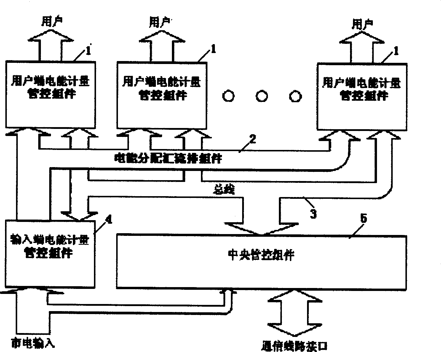
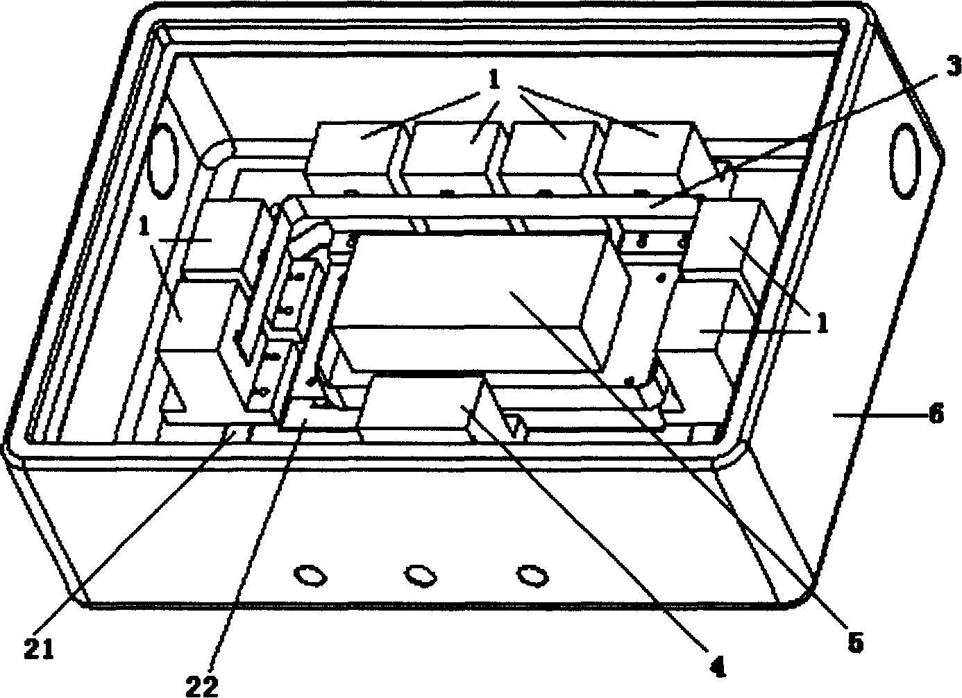
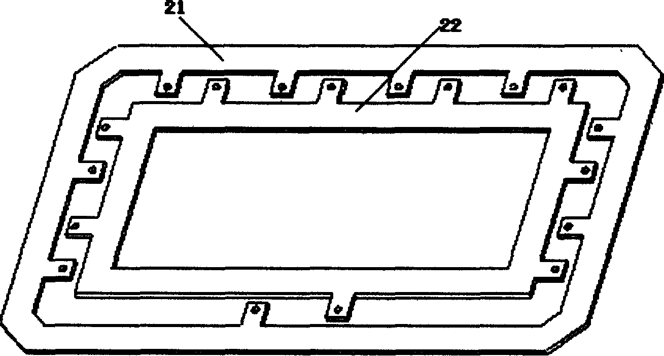
[0016] join figure 1 , 2 , the present invention combines an electric energy distribution busbar assembly 2, an input end electric energy metering management and control assembly 4, 1 to 30 user end electric energy metering management and control assemblies 1, and a central management and control assembly that provides shared display, control, communication and management functions for multiple users 5 are centrally placed in a closed box 6, and the input end electric energy metering control component 4, each group of user end electric energy metering control components 1 and the central control component 5 are connected by the bus 3. The management and control mentioned in the present invention all refer to management control. The specific number of user-end electric energy metering control components 1 can be determined according to actual application conditions during production, and generally 1 to 30 groups can be used by one building unit. A small part of the mains inpu...


PUM


Abstract

The metering device includes electric energy distribution bus, management and control unit of measuring electric energy at input end, and management and control unit of measuring electric energy at user end. Control unit of measuring electric energy at user end for 1-30 grouped users, central management and control unit of providing functions of display, control, communication and management for users in group are assembled inside a case. The said bus connects the control unit of measuring electric energy at input end, control unit of measuring electric energy at user end for 1-30 grouped users, and central management and control unit.

Description

technical field [0001] The invention relates to a low-voltage power supply management device, in particular to a centralized electric energy control and metering device. Background technique [0002] my country's electricity market and technology are developing rapidly, but management methods are seriously lagging behind, especially issues such as billing, electricity theft prevention, and safe use of electricity have long plagued power network operators and managers. At present, the measurement management of the low-voltage power supply system for residents usually adopts the outdated model of one household, one meter, and manual meter reading. The construction cost is high, the wiring scheme is complicated, the living space of the residents is occupied, and the meter reading work is inefficient and intensive. The distributed power transmission structure established corresponding to this measurement management mode is not conducive to flexible networking and online maintena...

Claims


Application Information

Patent Timeline
IPC IPC(8): G07F19/00H02B1/20H02J13/00
Inventor 张学斌
Owner 张学斌
Learn More