Check patentability & draft patents in minutes with Patsnap Eureka AI!

Optical projection system

A projection optical system and projection light technology, applied in the field of projection optical systems, can solve the problems of imaging performance degradation, easy distortion, unfavorable exposure performance, etc.

Inactive Publication Date: 2005-02-02
ORC MFG
View PDF2 Cites 5 Cited by
  • Summary
  • Abstract
  • Description
  • Claims
  • Application Information

AI Technical Summary

Problems solved by technology

[0014] However, in the catadioptric projection optical system 50 disclosed in JP-A-10-509561, since the magnification of the pattern imaged on the workpiece is adjusted by mechanically bending (buckling) the light-transmitting plates 52 and 58, the Stress generated when the light-transmitting plates 52 and 58 are bent causes bending fatigue of the light-transmitting plates themselves, so there is a problem that stable magnification adjustment cannot be performed.
[0015] Also, in the catadioptric projection optical system 60 disclosed in Japanese Patent Laid-Open No. 8-179217, the magnification adjustment system moves the plano-convex lens 72 through the adjuster 73. Since the plano-convex lens 71 and the plano-convex lens 72 arranged on the prism side The separation distance is adjusted, so there is a problem of distortion (distortion)
[0016] Also, in the known reflection correcting optical system, since the cemented lens is used in the optical system, although it is beneficial to correct the chromatic aberration, in the case of using ultraviolet light for projection light, the joint of the lens deteriorates the imaging performance, that is, in order to obtain Ideal imaging and aberration changes implemented by deviations are not conducive to meeting the required exposure performance

Method used


Image

  • Optical projection system
  • Optical projection system
  • Optical projection system

Examples


Embodiment Construction

[0042] Hereinafter, embodiments of the present invention will be described with reference to the drawings.

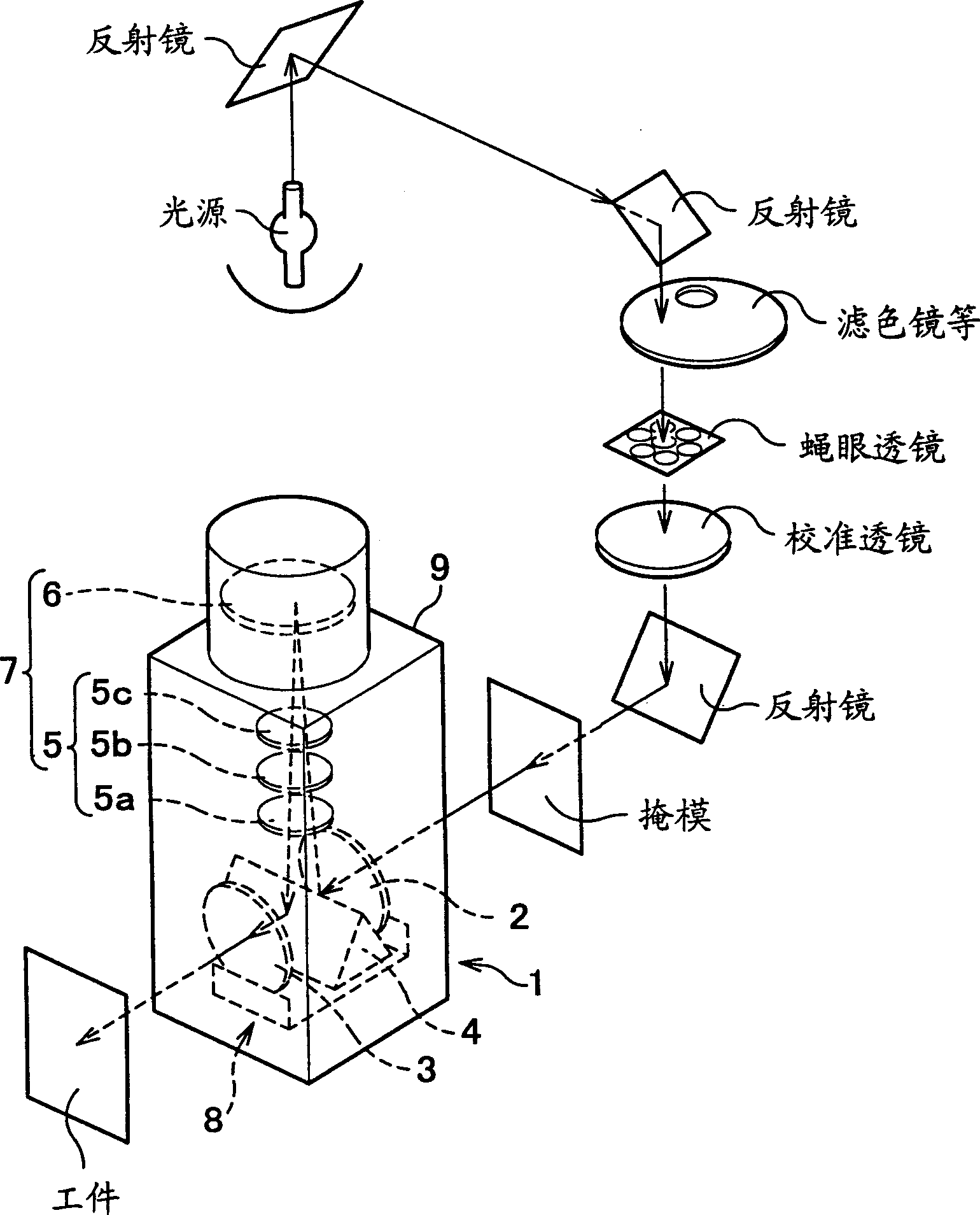
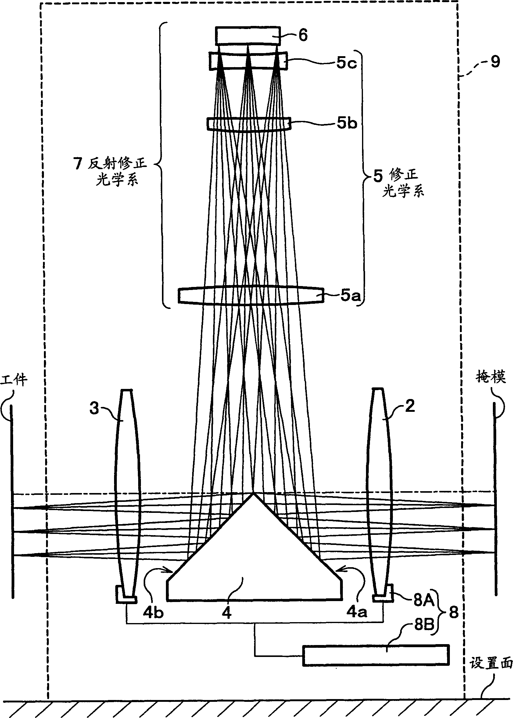
[0043] figure 1 is a perspective view of the configuration of the projection optical system, figure 2 It is a cross-sectional view showing the entire projection optical system.

[0044] Such as figure 1 As shown, the projection optical system 1 is arranged between the mask and the workpiece of the projection exposure device. Then, if figure 2 As shown, the projection optical system 1 includes an incident side convex lens 2 , an exit side convex lens 3 , a reflector 4 , a reflection correction optical system 7 , a support movement mechanism 8 and a frame body 9 .

[0045] The incident-side convex lens 2 and the exit-side convex lens 3 are formed coaxially and separated by a predetermined distance, and are installed on the moving mechanism 8 . The reflector 4 is located between the incident-side convex lens 2 and the exit-side convex lens 3 .

[0046] In this pro...


PUM

PropertyMeasurementUnit
angle of incidenceaaaaaaaaaa

Abstract

The invention relates to a projection optical system for a projection exposure device, which is applied to expose specified patterns on a printed circuit board, a LCD substrate and other workpieces. A projection optical system (1) comprises a reflector (4), a convex lens on an incidence side (2), a convex lens on an exit side (3), a support and movement apparatus (8) and a reflection correction optical system (7); wherein, the reflector (4) comprises a second reflecting surface (4b) and a first reflecting surface (4a) for changing the advancing direction of projection light; the convex lens on an incidence side (2) enables the projection light to pass in terms of refraction and guiding the light to the first reflecting surface of the reflector; the convex lens on an exit side (3) enables the projection light reflected by the second reflecting surface of the reflector to emit; the support and movement apparatus (8) is used for coaxially supporting the two convex lens with specified distance and enabling the two convex lens to move in parallel in an direction vertical to an optical axis; the reflection correction optical system (7) is composed of a concave mirror (6) and a correction optical system (5), enables the reflection light reflected by the first reflecting surface reflect to the second reflecting surface. The projection optical system for the projection exposure device has the advantages of reuding deformation of patterns and ensuring quality of imaging during adjustment of multiplying factor.

Description

technical field [0001] The present invention relates to a projection optical system, and more particularly relates to projecting illumination light such as ultraviolet light passing through a mask as projection light onto workpieces such as a printed circuit light-transmitting plate and an LCD-based light-transmitting plate, so that a predetermined pattern is displayed. A projection optical system for projecting exposure onto a workpiece. Background technique [0002] Conventionally, as an exposure device for forming patterns of electronic circuits, such as color filters for liquid crystals, on a transparent plate for a printed circuit or a transparent plate for a liquid crystal panel, a projection exposure device that performs exposure processing using ultraviolet light having a predetermined wavelength is generally used. . [0003] Furthermore, various proposals have been made as a projection optical system or a catadioptric projection optical system (hereinafter, simply ...

Claims


Application Information

Patent Timeline
Patent Type & Authority Applications(China)
IPC IPC(8): G02B17/08G02B13/24G02B27/00G03F7/20H01L21/027
CPCG02B27/0043G03F7/70258G03F7/20
Inventor 李
Owner ORC MFG
Features
  • R&D
  • Intellectual Property
  • Life Sciences
  • Materials
  • Tech Scout
  • Unparalleled Data Quality
  • Higher Quality Content
  • 60% Fewer Hallucinations
Learn More