Combustion control apparatus for internal combustion engine

A technology for internal combustion engines and control equipment, which is applied in engine control, internal combustion piston engines, combustion engines, etc., and can solve problems such as increased engine back pressure

Inactive Publication Date: 2005-02-09
NISSAN MOTOR CO LTD
View PDF1 Cites 17 Cited by
  • Summary
  • Abstract
  • Description
  • Claims
  • Application Information

AI Technical Summary

Problems solved by technology

When the accumulated amount of PM in the particulate filter exceeds a specified amount, the back pressure of the engine rises, causing trouble in operation

Method used


Image

  • Combustion control apparatus for internal combustion engine
  • Combustion control apparatus for internal combustion engine
  • Combustion control apparatus for internal combustion engine

Examples


Embodiment Construction

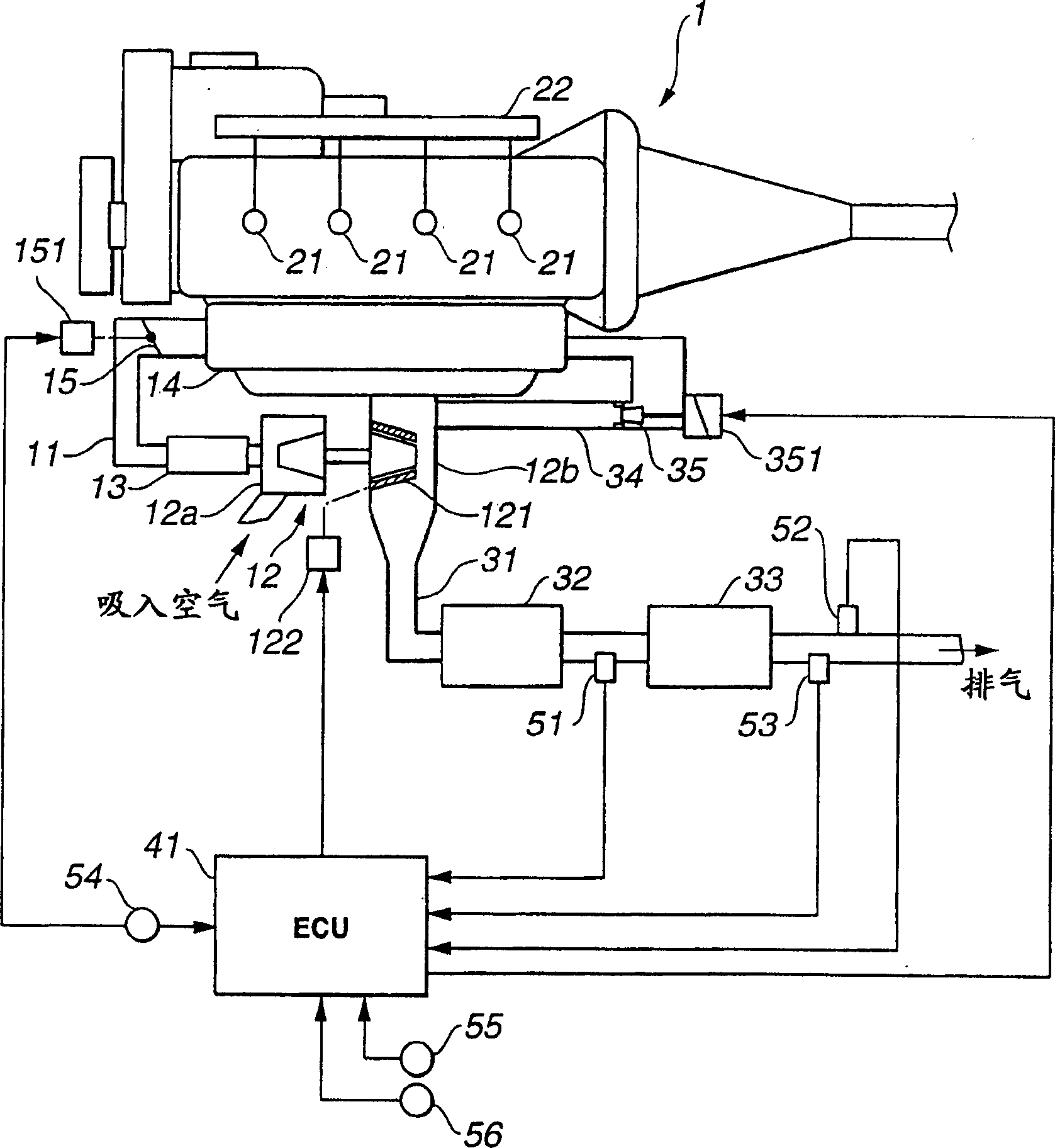
[0052] see now figure 1 , which shows a diesel engine including a combustion control apparatus according to an embodiment of the present invention. Intake air flows in through an air filter (not shown) arranged at the inlet of the intake passage 11 . Air filters remove dust particles from the intake air. A compressor 12 a of a variable nozzle turbocharger 12 is arranged in the intake passage 11 to compress the intake air. An intercooler 13 is arranged downstream of the compressor 12a, which cools the compressed intake air. After cooling, the sucked air flows to the surge tank 14 . Surge tank 14 includes a manifold section for distributing intake air to the cylinders. Upstream of the buffer tank 14 is arranged a throttle valve 15 that changes the flow rate of the sucked air. The throttle valve 15A is connected to a throttle valve actuator 151 to adjust its opening degree.

[0053] A fuel injector 21 for each cylinder is arranged in a cylinder head of the engine 1 . Fuel ...


PUM


Abstract

A combustion control apparatus operates an internal combustion engine in a split retard combustion mode during regenerating an exhaust purifier such as a particulate filter. In the split retard combustion mode, the combustion control apparatus controls a first fuel injection to cause preliminary combustion at or near top dead center, and controls a second fuel injection to cause main combustion after an end of the preliminary combustion. In this manner, the combustion control apparatus controls an exhaust gas temperature, or an exhaust air-fuel ratio, without increasing exhaust smoke. During the split retard combustion mode, the combustion control apparatus controls an EGR rate of the engine. The EGR rate in the split retard combustion mode is set lower than in the normal combustion mode, in each operating point of the engine.

Description

technical field [0001] The present invention relates generally to a control device for an internal combustion engine, and in particular to a combustion control device for an internal combustion engine with an exhaust cleaner such as a particulate filter, configured to reduce the excess air ratio of the engine and increase the Exhaust temperature without increasing exhaust smoke. Background technique [0002] In recent years, for an engine with an exhaust gas cleaner in an exhaust passage, various techniques for increasing the temperature of the exhaust gas to activate the exhaust gas cleaner have been disclosed. Such a technique is disclosed in Japanese Patent Provisional Publication No. 2000-320386, particularly in sections [0106] to [0111]. In this technique, the basic fuel injection quantity that produces the required engine torque is calculated based on the operating state of the engine. A base fuel injection quantity of fuel is provided to cylinders of the engine thro...

Claims


Application Information

Patent Timeline
Patent Type & Authority Applications(China)
IPC IPC(8): F02D41/00F02D41/02F02D41/40
CPCF02D41/40F02D41/027Y02T10/44F02D2200/0802F02D41/028F02D41/005Y02T10/47F02D41/029F02D41/0275F02D41/403Y02T10/40
Inventor 北原靖久
Owner NISSAN MOTOR CO LTD
Why Eureka
Try Eureka