
Cathode ray tube

A cathode ray tube, diagonal technology, applied in the direction of cathode ray tube/electron beam tube, cathode ray/electron beam tube casing/container, discharge tube, etc., can solve the problem of reducing the shadow mask plate 108, the shadow mask plate 108 Structural strength reduction, etc.

Inactive Publication Date: 2005-02-09
MERIDIAN SOLAR & DISPLAY
View PDF0 Cites 0 Cited by
  • Summary
  • Abstract
  • Description
  • Claims
  • Application Information

AI Technical Summary

Problems solved by technology

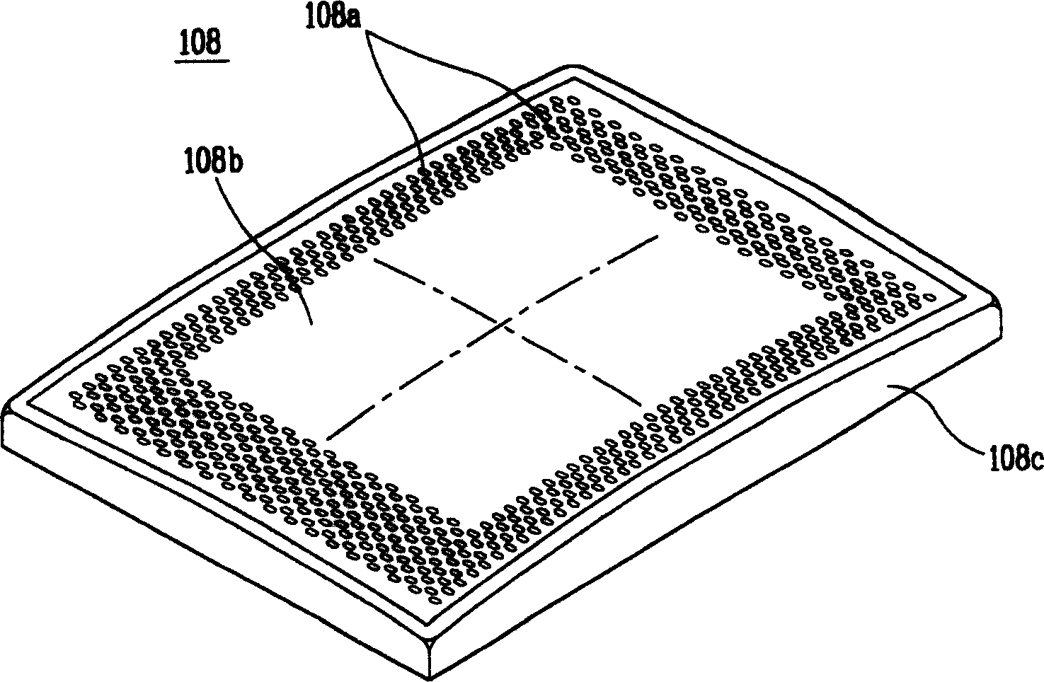
[0009] Also, even if a method of reducing the thickness of the shadow mask 108 in order to reduce weight and material costs is considered, there is a limit to reducing the thickness of the shadow mask 108, and therefore, it is insufficient due to the reduction in the structural strength of the shadow mask 108.

Method used


Image

  • Cathode ray tube
  • Cathode ray tube
  • Cathode ray tube

Examples


Embodiment Construction

[0027] Now, preferred embodiments according to the present invention will be described in detail, and examples will be illustrated in the accompanying drawings.

[0028] as in Figure 5 As shown in, a cathode ray tube (CRT) includes: a panel 1 made of front glass whose outer surface is substantially flat and whose inner surface has a predetermined curvature; a funnel-shaped device 2 engaged with the panel 1 and made of rear glass, For forming a vacuum space; a phosphor screen 13 placed on the inner surface of the panel 1, and used to emit fluorescence; an electron gun 6 for emitting electron beams 5 that make the phosphor screen 13 emit light; a funnel-shaped device installed A deflection coil 7 with a predetermined interval on the peripheral surface of 2 is used to deflect the electron beam 5 to the fluorescent screen 13; a shadow mask 8 installed on a certain distance from the fluorescent screen 13; a yoke for fixing and supporting the shadow mask 8 a shadow mask frame 9; a...


PUM


Abstract

A cathode ray tube comprising a panel of which an outer surface is substantially flat and an inner surface has a certain curvature, and a shadow mask arranged with a certain interval from an inner surface of the panel and having a plurality of apertures through which electron beams pass, wherein the shadow mask satisfied a condition of 0.9<=ZmD / (ZmX+ZmY)<=1.1, in which an arbitrary point on a diagonal axis of the shadow mask is supposed to be Dr, points on a long axis and a short axis meeting with perpendiculars drawn to the long axis and the short axis from the point Dr are respectively supposed to be Xr and Yr, and intervals between the respective points Xr, Yr, and Dr and the shadow mask in a tube axis direction are respectively supposed to be ZmX, ZmY, and ZmD.

Description

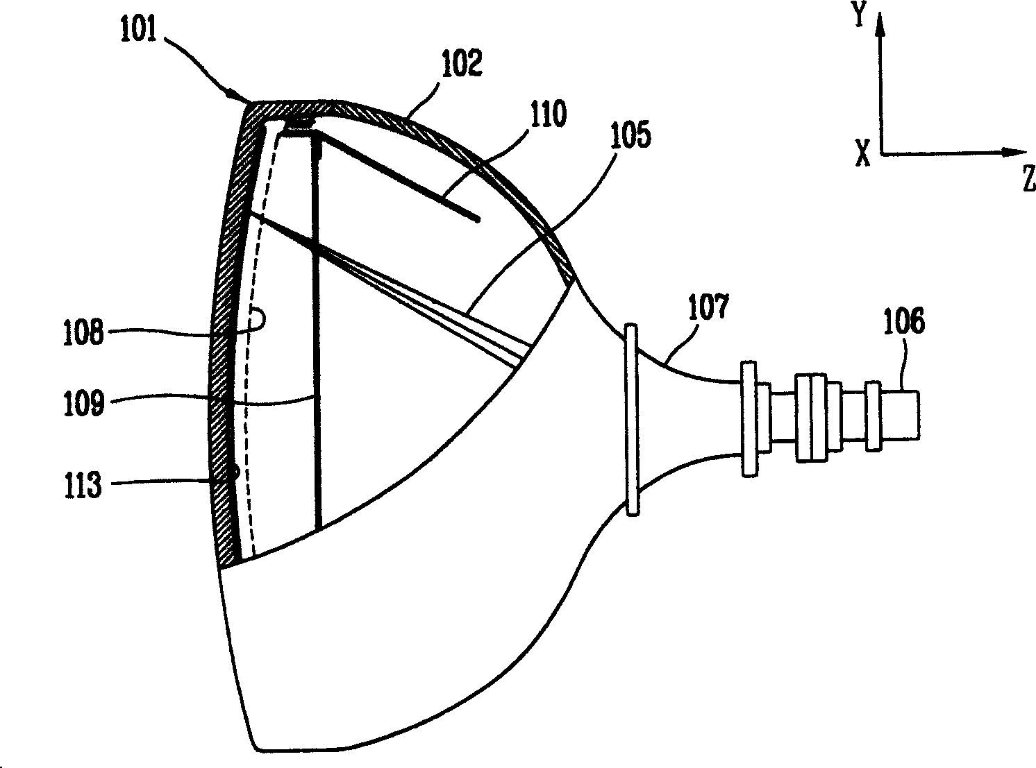
technical field [0001] The present invention relates to a cathode ray tube, and more particularly to a cathode ray tube capable of improving the characteristics of a shadow mask by optimizing the structural strength of the shadow mask. Background technique [0002] A cathode ray tube is a device that converts electrical signals into electron beams and emits the electron beams to a fluorescent screen to generate images. Cathode ray tubes are widely used in conventional technology due to the ability to obtain good display quality at an affordable price. [0003] Now, a cathode ray tube will be explained with reference to the drawings. figure 1 is a schematic diagram illustrating an example of a conventional art cathode ray tube. Such as figure 1 As shown in , the cathode ray tube includes: a panel 101 made of front glass; a funnel-shaped device 102 made of rear glass engaged with the panel 101 for forming a vacuum space; a fluorescent screen 113, which is placed on the pane...

Claims


Application Information

Patent Timeline
Patent Type & Authority Applications(China)
IPC IPC(8): H01J29/07H01J29/80H01J29/81H01J29/86
CPCH01J29/861H01J29/07H01J2229/0788H01J2229/862
Inventor 郑勋
Owner MERIDIAN SOLAR & DISPLAY
Learn More