
Static suspension rotor micro inertia sensor and its manufacturing method

A technology of micro-inertial sensor and electrostatic levitation, applied in the direction of rotating gyroscope, etc., can solve the problems of high equipment cost, poor side wall flatness, complicated process, etc., and achieve the effect of simple structure and low manufacturing cost

Inactive Publication Date: 2005-02-16
SHANGHAI JIAO TONG UNIV
View PDF1 Cites 12 Cited by
  • Summary
  • Abstract
  • Description
  • Claims
  • Application Information

AI Technical Summary

Problems solved by technology

The main disadvantages of the ICP DRIE process are complex process, high equipment cost, and poor flatness of the etched bulk silicon sidewall. In order to reduce the surface roughness of the sidewall to prevent localized discharge breakdown in the radial gap, ICP DRIE etch Strict process parameter control is required for silicon

Method used


Image

  • Static suspension rotor micro inertia sensor and its manufacturing method
  • Static suspension rotor micro inertia sensor and its manufacturing method
  • Static suspension rotor micro inertia sensor and its manufacturing method

Examples


Embodiment Construction

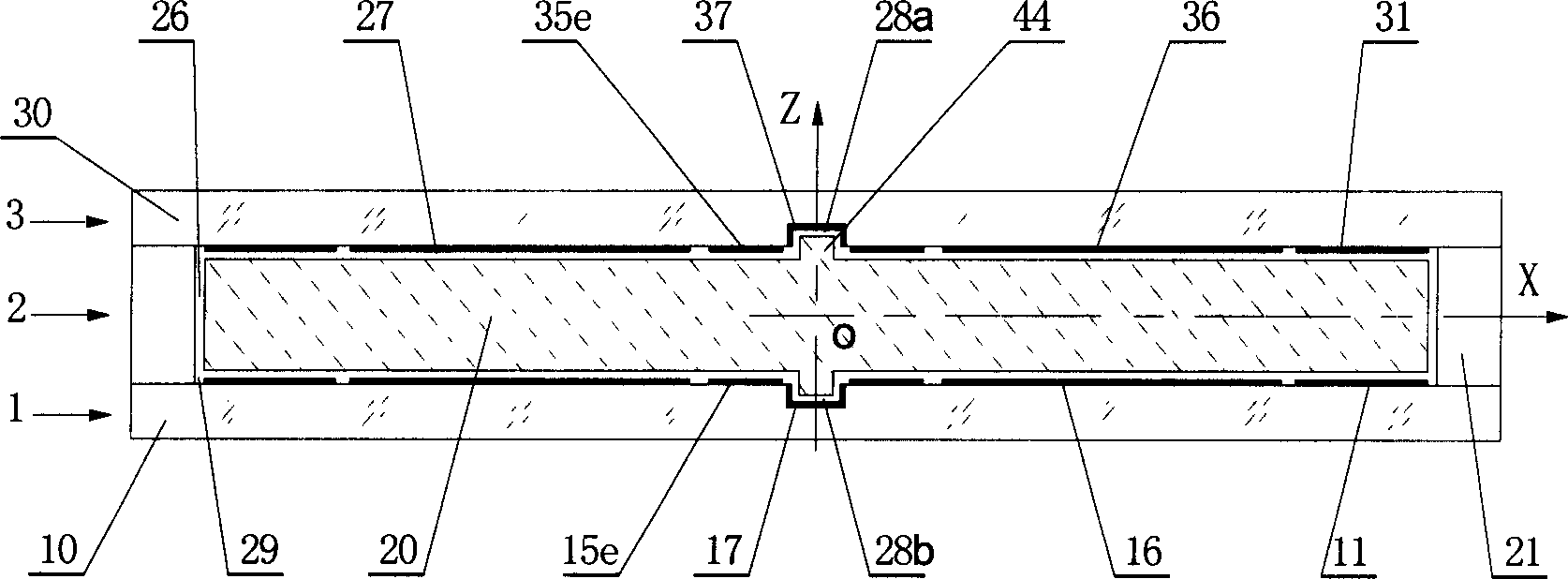
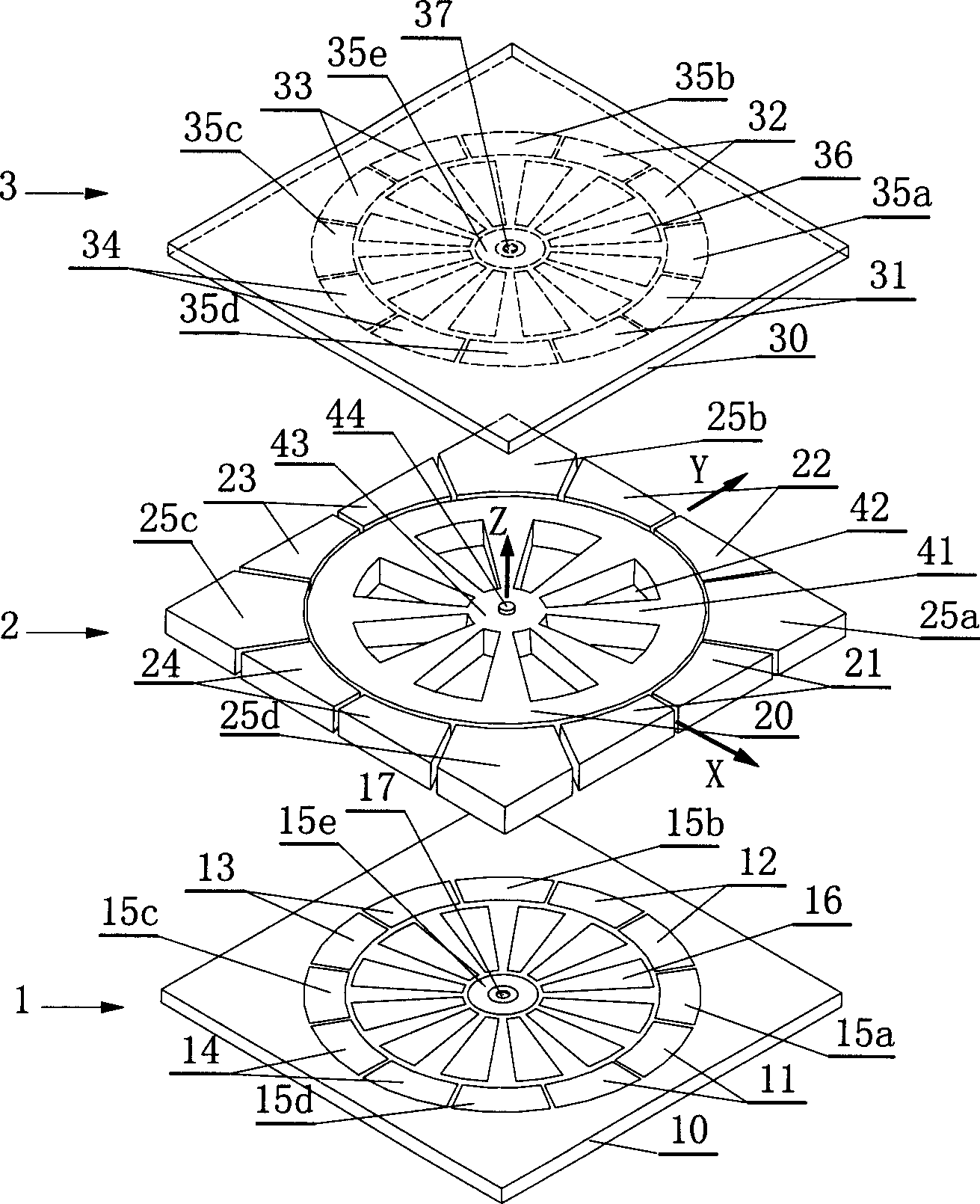
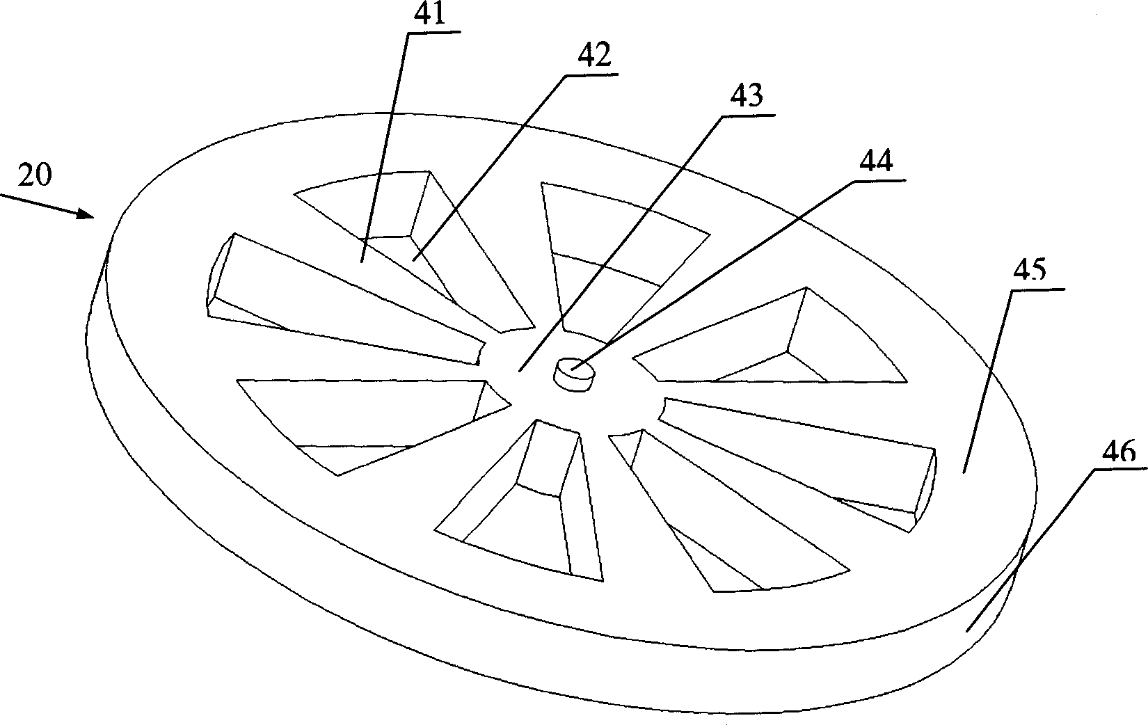
[0016] Such as figure 1 , figure 2 As shown, the present invention adopts a sandwich-type three-layer bonding structure, which is composed of a lower substrate layer 1 , an intermediate metal structure layer 2 and an upper substrate layer 3 . On the upper surface of the substrate 10 of the lower substrate layer 1, axial thin-film metal electrodes and leads are arranged, wherein the axial thin-film metal electrodes include axial suspension control electrode pairs 11, 13 arranged along the X-axis, and arranged along the Y-axis Axial levitation control electrode pairs 12, 14, common electrodes 15a-15e and rotation driven stator electrodes 16 whose number is a multiple of three; a stop pit 17 is also provided at the center of the lower substrate 10. The upper substrate layer 3 has the same structure as the lower substrate layer 1, and the lower bottom surface of the substrate 30 is also provided with axial suspension control electrode pairs 31, 33 arranged along the X axis, and ...


PUM


Abstract

This is a static suspension rotator mini inertial sensor and its productive method. It comprises lower lining layer, the middle metal constructive layer and upper lining layer. The middle metal constructive layer comprises metal rotator and arouncd it there are a rotator cavity and radial electric poles, the lower and upper lining layer are bonded with the radial electric poles separately to form the rotator cavity. The wheel type metal rotator locates at the center of the rotator cavity. Between the lower and upper axial electric poles, which on the lower and upper lining layer, and between the rounded radial electric poles there are axial electric pole gap and radial electric pole gap. This mini inertial sensor's productive method contains: The working order of lower lining layer, and middle metal constructive layer, and upper lining layer, and the working order of bonded together, or include the working order of lower lining layer, upper lining layer, radial electric pole, metal rotator working order and mini assemble working order and bonded working order, to give out the productive method which base to UV-LIGA technology.

Description

technical field [0001] The invention relates to a micro-inertial sensor and a manufacturing method thereof, in particular to an electrostatic levitation rotor micro-inertial sensor and a manufacturing method thereof, which are used in the technical field of micro-electromechanical systems. Background technique [0002] Electrostatic suspended rotor micro-inertial sensor is a kind of micro-mechanical inertial sensor that is different from vibrating micro-gyro and general micro-accelerometer. The principle of rotating drive) as the detection mass, the gyro effect generated by the high-speed rotation of the suspended micro-rotor, and the input two-axis angular velocity is measured by the principle of torque rebalance; at the same time, the three-axis acceleration can be measured by the suspended micro-rotor by means of the principle of force balance. A micro-inertial sensor that uses a suspended micro-rotor as a proof mass to measure angular velocity and linear acceleration has...

Claims


Application Information

Patent Timeline
IPC IPC(8): G01C19/24
Inventor 陈文元崔峰赵小林张卫平
Owner SHANGHAI JIAO TONG UNIV
Learn More