Motor iron core, motor and method for manufacturing motor ironcore

A technology for electric motors and iron cores, which is applied in the manufacture of stator/rotor bodies, magnetic circuit shapes/styles/structures, and magnetic circuit static parts, etc. problem, achieve the effect of reducing cogging torque and torque ripple, preventing the decline of magnetic properties, and improving the bending precision

Inactive Publication Date: 2005-02-16
NIDEC SHIBAURA CORP
View PDF0 Cites 6 Cited by
  • Summary
  • Abstract
  • Description
  • Claims
  • Application Information

AI Technical Summary

Problems solved by technology

For this reason, when the steel plate is punched, the impact strength of the punching die decreases at the protruding parts 116, 116' of the steel plate, the wear and damage of the punching die locally becomes larger, and the life of the die decreases, resulting in depreciation and maintenance costs of the punching die. , Increase in equipment maintenance costs and other cost increases
[0007] When the diameter of the hole portion 114 is increased in order to achieve the above-mentioned uniformity of impact strength, the cross-sectional area of ​​the core bending portion 112 serving as a magnetic path between the tooth portions 111 decreases, the magnetic resistance increases, and the magnetic properties deteriorate. When reducing the reluctance, it is necessary to increase the size of the iron core itself, and there is a problem that the motor becomes larger
[0008] In addition, when the above-mentioned straight core 100 is bent to form an annular core, as Figure 12 As shown in (a) and (b), the front ends of the steel plate protrusions 116 and 116' on both sides of the beveled portion 118 serve as the bending fulcrum of the core bending portion 112, and the deformation pressure is locally concentrated, and the deformation pressure is generated in the steel plate. Large strain, in addition, in addition, the strain deformation region also expands, the iron loss of the core bending part 112 that becomes the magnetic circuit increases, and the magnetic characteristics are reduced
[0009] In addition, the occurrence of processing strain when bending the core bending portion 112 or its deviation reduces the shape accuracy (such as roundness, concentricity, coaxiality, etc.) of the ring core, causing noise and vibration of the motor using it.

Method used


Image

  • Motor iron core, motor and method for manufacturing motor ironcore
  • Motor iron core, motor and method for manufacturing motor ironcore
  • Motor iron core, motor and method for manufacturing motor ironcore

Examples


Embodiment Construction

[0033] (first embodiment)

[0034] The following is based on Figure 1-7 A first embodiment of the present invention will be described.

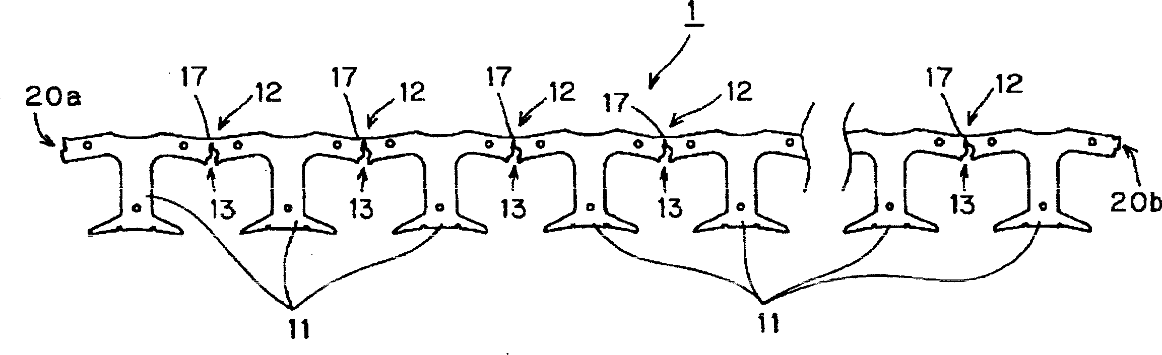
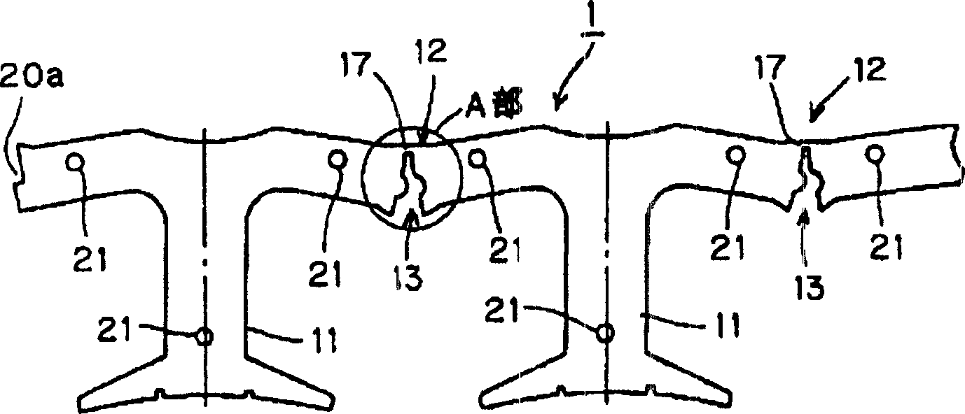
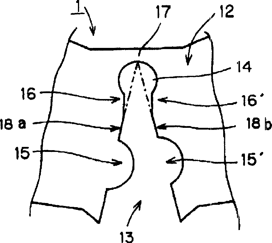
[0035] figure 1 It is a plan view of the straight core 1 constituting the core of the brushless DC motor. figure 2 for figure 1 A partially enlarged view of the straight iron core 1 shown, image 3 It is a V-shaped notch provided on the bending part of the core ( figure 2 A magnified view of part A).

[0036] Such as figure 1 , 2 As shown, a straight iron core 1 is formed by punching laminated silicon steel sheets with a press using a punching die, and a plurality of T-shaped tooth portions 11 pass through the notch of the core bending portion 12 having a V-shaped notch portion 13 The narrow connecting portion 17 at the bottom of the portion 13 is connected in a strip shape, and the screw hole 21 is opened at a predetermined position, and the connecting portions 20a, 20b for bending the straight core 1 to be connected in a ring ...


PUM


Abstract

Multiple teeth part 11 of straight type iron core 1 through edgefold 12 of V shape notch 13 is connected. Hole part 14 is setup in front of notch 13. Concavo-convex shaped bulge is setup on faces in opposite direction in V shape notch 13. Strain avoiding notches 16, 16' are formed under hole part 14. Advantages are: raising life time of cutting die, reducing strain of bending work, maintaining magnetic characteristic and raising manufacturing accuracy.

Description

technical field [0001] The present invention relates to a motor core used for a motor such as a brushless DC motor, a motor using the core, and a method for manufacturing the motor core. Background technique [0002] The iron core of a commonly used electric motor is formed in an annular shape by laminating a plurality of straight iron cores, and the straight iron cores are connected with a plurality of teeth punched out of silicon steel plates in a belt shape. [0003] The following is based on Figure 10 The partial plan view of strip straight core 100 is shown to illustrate straight cores of the past. The straight core 100 is formed by connecting a plurality of tooth portions 111 in a belt shape through a core bending portion 112 having a V-shaped notch portion 113 , and punching out laminated silicon steel sheets. [0004] The motor core is formed into a ring shape by bending the core bending portion 112 of the straight core 100 in a direction to close the V-shaped notc...

Claims


Application Information

Patent Timeline
IPC IPC(8): H02K1/16H02K15/02
Inventor 村上卓也村上俊明
Owner NIDEC SHIBAURA CORP
Why Eureka
Try Eureka