Vacuum casting furnace main shaft lifting rod protection device

A technology of protection device and lifting rod, applied in the direction of casting mold, casting mold composition, casting equipment, etc., can solve the problem of shortening the service life of the spindle, and achieve the effect of reducing the number of maintenance and cost, improving the applicability and improving the use efficiency.

Pending Publication Date: 2022-03-22
AECC AVIATION POWER CO LTD
View PDF8 Cites 0 Cited by
  • Summary
  • Abstract
  • Description
  • Claims
  • Application Information

AI Technical Summary

Problems solved by technology

[0004] Aiming at the problem in the prior art that the main shaft lifting rod has metal shavings splashing during operation, which causes the surface of the main shaft system to wear and shorten the service life of the main shaft system, the present invention provides a protection device for the main shaft lifting rod of a vacuum melting casting furnace. The device has a simple structure. It is easy to use, effectively prevents the spindle surface from being damaged by the splashed metal liquid and shortens the service life of the spindle, solves the inconvenience of cleaning metal chips on the surface of the spindle and prolongs the service life of the spindle, and solves the seal between the spindle lifting rod and the casting chamber , coordination and other technical problems

Method used


Image

  • Vacuum casting furnace main shaft lifting rod protection device

Examples


Embodiment 1

[0052] ALD three-chamber vacuum furnace

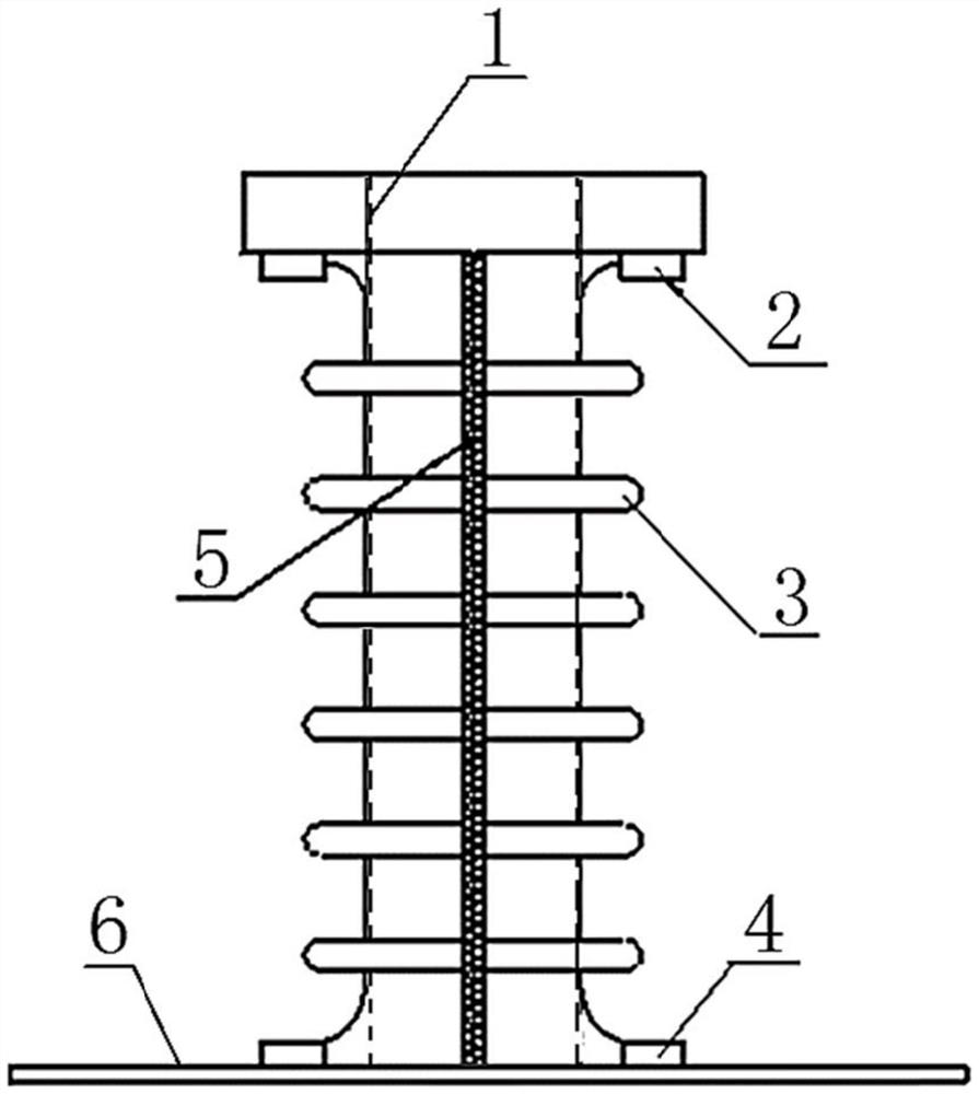
[0053] 1) Make a protective cover 2 matching the main shaft of the ALD furnace, and arrange an elastic refractory plastic material along the axial direction of the main shaft.

[0054] 2) Make the first fixing part 2 and the second fixing part 4 in the present invention, so that the top end of the protective cover 2 can be tightly connected with the bottom surface of the lifting rod table through the first fixing part 2, and the bottom end can pass through the second fixing part for one week. Part 4 is seamlessly connected with pit 6.

[0055] 3) Make the zipper 5 of the present invention, zip it from top to bottom along the axial direction of the protective cover 2, connect the protective cover 2 for one week, and keep the gap between the main shaft elevating rod 1 and the protective cover 2 at 12mm.

[0056] 4) Install the manufactured lifting rod corrugated protective cover on the outside of the main shaft lifting rod 1, fasten the...

Embodiment 2

[0060] 1) Make a supporting protective cover 2 for a large-scale 100kg vacuum furnace, and arrange an elastic refractory plastic material along the axial direction of the main shaft.

[0061] 2) Make the first fixing part 2 and the second fixing part 4 in the present invention, so that the top end of the protective cover 2 can be tightly connected with the bottom surface of the lifting rod table through the first fixing part 2, and the bottom end can pass through the second fixing part for one week. Part 4 is seamlessly connected with pit 6.

[0062] 3) Make the zipper 5 of the present invention, zip from top to bottom along the axial direction of the protective cover 2, connect the protective cover 2 for one week, and keep the gap between the main shaft elevating rod 1 and the protective cover 2 at 15 mm.

[0063] 4) Install the manufactured lifting rod corrugated protective cover on the outside of the main shaft lifting rod 1, fasten the upper and lower ends with four bolts ...


PUM


Abstract

The invention provides a protection device for a spindle lifting rod of a vacuum casting furnace, relates to the field of precision investment casting vacuum casting furnaces, and relates to aviation and aerospace engines, in particular to the protection device for the spindle lifting rod of the vacuum casting furnace, which is arranged along the vertical direction of the spindle lifting rod and wraps a protection sleeve outside the spindle lifting rod. The spindle system is not damaged by splashed metal when the spindle lifting rod conveys a mold shell and is poured, meanwhile, the protective sleeve plays a role in protecting the spindle lifting rod, and the problems that the spindle is abraded and damaged by metal chips when the spindle lifting rod reciprocates and the maintenance cost of the spindle system is high can be effectively solved; the maintenance frequency and cost of the spindle system are reduced, the use efficiency of vacuum casting furnace equipment is improved to a great extent, the situation that the service life of the spindle is shortened due to the fact that the surface of the spindle is damaged by adhesion of splashed molten metal is effectively avoided, and the problems that metal filings on the surface of the spindle are inconvenient to clean and the service life of the spindle is prolonged are solved.

Description

technical field [0001] The invention relates to the field of investment casting precision casting vacuum melting furnaces, and relates to aviation and aerospace engines, in particular to a protection device for a main shaft lifting rod of a vacuum melting casting furnace, which is used to protect the safety and reliability of the core part of the main shaft system. Background technique [0002] Some investment precision castings require vacuum in the environment during pouring, so they need to be poured in vacuum casting equipment. The main content of the vacuum pouring process is to pour the liquid whose melting temperature reaches the required temperature into the mold shell that reaches the specified temperature in the equipment with a vacuum degree that meets the requirements. [0003] During the pouring process, the form shell is raised to the pouring chamber through the main shaft lifting rod. If the pouring operation is improper, the high-temperature liquid above the ...

Claims


Application Information

Patent Timeline
Patent Type & Authority Applications(China)
IPC IPC(8): B22D33/02B22D27/15B22C9/04
CPCB22D33/02B22D27/15B22C9/04
Inventor 张妮潘锐王玮王凡常涛岐任怀远丁小科刘轩
Owner AECC AVIATION POWER CO LTD
Why Eureka
Try Eureka