Crawler-type walking rockbolt drilling carriages

A rock bolt drilling rig and walking technology, which is applied in the installation of bolts, drilling equipment, earthwork drilling, etc., can solve the problems of complex structure, high price and high failure rate.

A rock bolt drilling rig and walking technology, which is applied in the installation of bolts, drilling equipment, earthwork drilling, etc., can solve the problems of complex structure, high price and high failure rate.

CN1584292AActive Publication Date: 2005-02-23TAIYUAN INST OF CHINA COAL TECH & ENG GROUP

Image

  • Crawler-type walking rockbolt drilling carriages
  • Crawler-type walking rockbolt drilling carriages
  • Crawler-type walking rockbolt drilling carriages

Examples


Embodiment Construction

[0037] The present invention will be further described below in conjunction with the accompanying drawings.

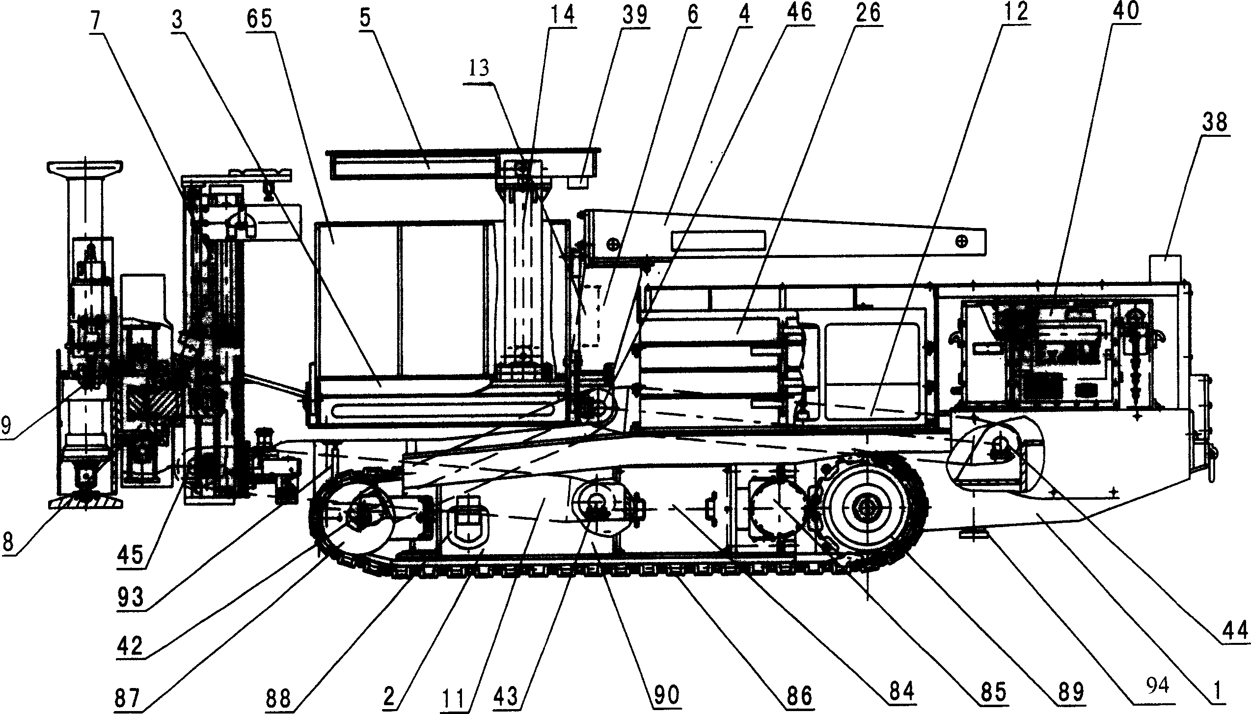
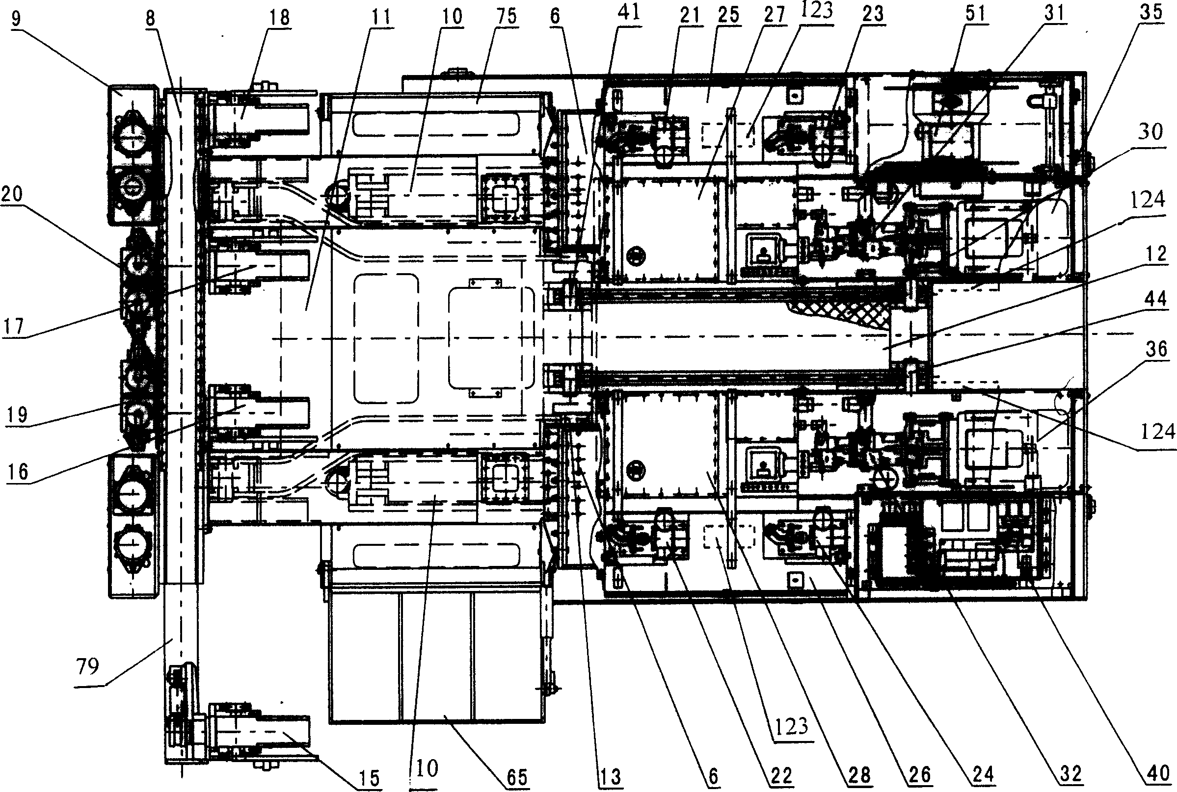
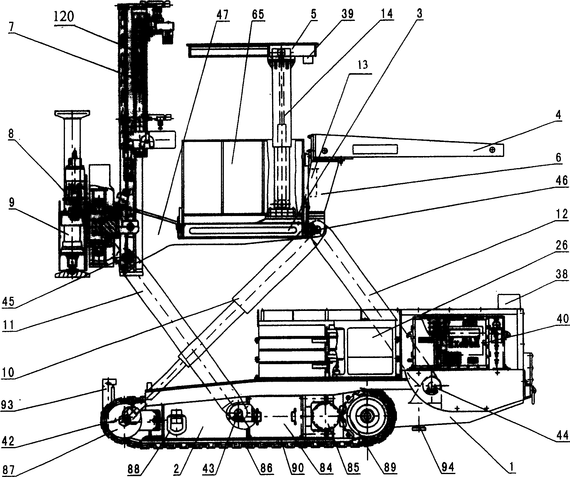
[0038] figure 1 , 2 As shown in , 3, this drilling rig is a large and heavy machinery with a dead weight of more than 40 tons. Since it works in the harsh environment of the underground, all electrical components have been designed for explosion-proof; machine base 1, traveling mechanism 2, workbench 3. Drill frame assembly 7, slide rail assembly 8, support assembly 9 and lifting mechanism form a complete machine model; , support assembly 9, hopper 4, material rack 6, ceiling 5, lifting frame oil cylinder 14 and the lifting mechanism fall, the height is reduced, the center of gravity is balanced, the machine base 1 and each mechanism are placed on the walking mechanism 2 on both sides, The machine is also in this state when it travels for a long distance, so the two traveling mechanisms 2 on the left and right are the load-bearing support center of gravity of the dri...


PUM


Abstract

The present invention relates to a crawler running roof-bolting jumbo for coal extraction in the pit. It mainly includes machine seat, working table, running mechanism, lifting mechanism, hydraulic mechanism, dust-removing mechanism, cable-rolling mechanism, drilling cramp component, slideway component, support component and electric control box, said whole machine adopts hydraulic transmission, automatic dust-removing, automatic cable-rolling and crawler running modes, and utilizes the hydraulic oil cylinder to control parallelogram lifting movement and can make moving, lifting and multi-arm roof-bolt drilling works in the excavating tunnel. Said invention is reasonable in structure, large in load-bearing capacity, reliable and high in working efficiency.

Description

technical field [0001] The invention relates to a crawler-type rock bolter, which belongs to the technical field of design and manufacture of roadway support anchor drilling equipment for underground mining in coal mines. Background technique [0002] In modern large-scale coal mines, the development and support of underground mining roadways is very important, and it is the main means for safe operation and prevention of coal seam subsidence. [0003] Roof bolters are commonly used mechanized support equipment in large coal mines. They mainly include bolters produced in Australia and the United Kingdom. There are no similar domestic models in China. At present, the bolters used in large coal mines in China mainly rely on imports. However, the technology blockade of imported equipment is relatively common, its structure is complex, the failure rate is high, maintenance is difficult, the supply cycle of vulnerable parts is long, and the price is high. Some key technologies do ...

Claims


Application Information

Patent Timeline
23 Feb 2005
Publication
CN1584292A
IPC
E21B7/02; E21D20/00
Inventors
雷煌; 王步康