Manufacturing process for energy-saving light electric cable bridge structure

A production process and technology of cable tray, which is applied in the field of production process of energy-saving lightweight cable tray, can solve the problem of not finding patent documents or materials, etc., and achieve the effect of low cost, reduced cost and reasonable structure

Active Publication Date: 2005-02-23
JIANGSU ONEQ ELECTRICAL APPLIANCE GRP
View PDF0 Cites 15 Cited by
  • Summary
  • Abstract
  • Description
  • Claims
  • Application Information

AI Technical Summary

Problems solved by technology

[0010] So far, no relevant patent documents or materials have been retrieved

Method used


Image

  • Manufacturing process for energy-saving light electric cable bridge structure
  • Manufacturing process for energy-saving light electric cable bridge structure

Examples


Embodiment Construction

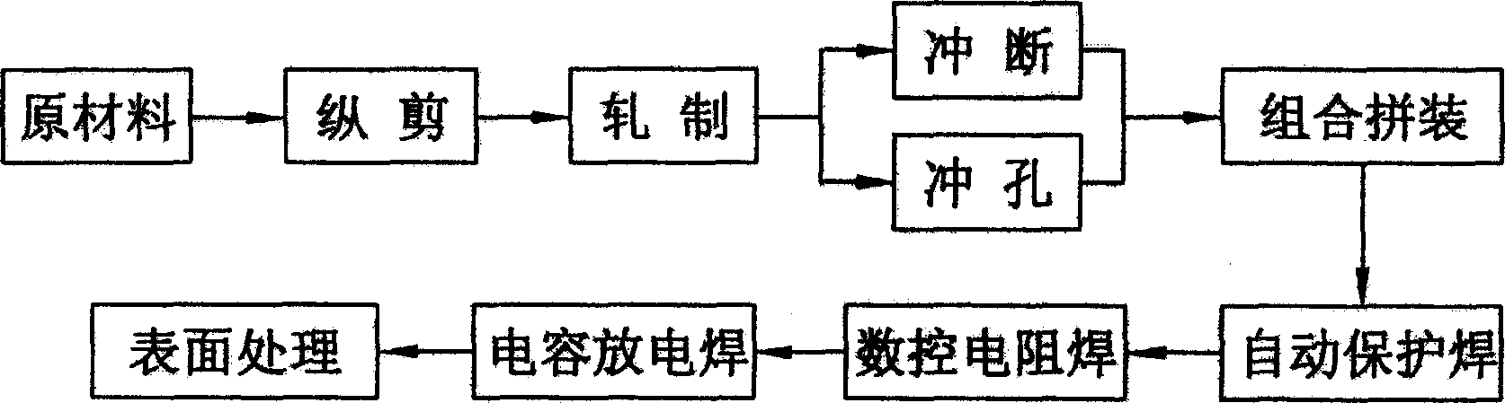
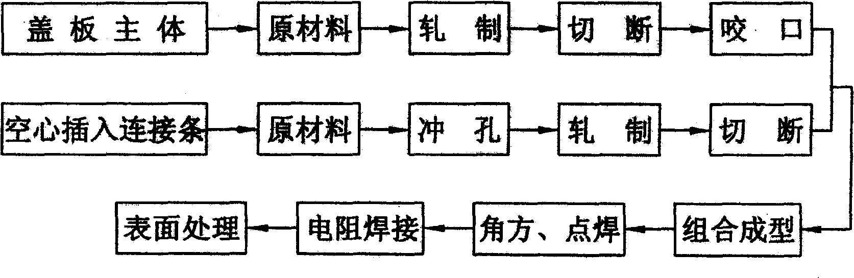
[0060] According to the process flow chart, the entire manufacturing process of energy-saving lightweight cable tray completely abandons the traditional product manufacturing process. The cold-rolled coil is cut into steel strips of fixed specifications by a slitting and slitting machine, and the stretching equipment is used to The steel strip is rolled into concave-convex corrugated bottom plate and U-shaped groove side by multiple rolls. The formed bottom plate is punched into strips according to the width of the bridge product, and the side plate is directly cut by the forming machine into the required bridge frame. The length of the two ends of the side plate and the bottom plate of the tray-type bridge frame are punched into fixed connections and cooling holes by a punching machine. The bottom plate is arranged in sequence and the length of the bridge frame and placed flat on the welding machine track, and the side plate is placed in a standing position. On both sides of t...


PUM


Abstract

An energy-saving production of electric cable bridge casings can reduce weight of products and costs, and improves performance of products while verifies functions of products. The casings consist of two parts, which are produced separately. Bridge bodies are produced by: cutting longitudinally, rolling, punching, assembling, and automatically welding. Radiation-cooled parts are produced by: rolling, cutting, holding-on, punching holes on inserted strips, rolling inserted strips for the upper pieces, cutting them, assembling, square-making, welding, and surface treating.

Description

technical field [0001] The invention relates to a production process for a cable bridge, in particular to a production process for an energy-saving lightweight cable bridge. Background technique [0002] Cable tray is a product used to support the laying of wires, cables, and pipe cables. Due to the low technical content of the bridge products, although some manufacturers have made some improvements to the production process and production efficiency, they have not fundamentally changed the bridge. The production process and structure of the product. We conduct in-depth exploration and research from the perspective of material mechanics and light steel structure. Changing the structure is an effective way to increase the rigidity of the steel plate. The strength of the steel plate can be increased through deformation, so that the thickness of the steel plate can be reduced during the product manufacturing process, and then the weight of the ...

Claims


Application Information

Patent Timeline
Patent Type & Authority Applications(China)
IPC IPC(8): F16L3/00
Inventor 马纪财
Owner JIANGSU ONEQ ELECTRICAL APPLIANCE GRP
Why Eureka
Try Eureka