

LED subdued planar panel displaying (illumination) devices
A light-emitting diode and flat-panel display technology, which is applied to identification devices, instruments, etc., can solve the problems of high cost and achieve the effect of changing colors, clear graphics, and strong three-dimensional state
- Summary
- Abstract
- Description
- Claims
- Application Information
AI Technical Summary
Problems solved by technology
Method used
Image

Examples
Embodiment Construction
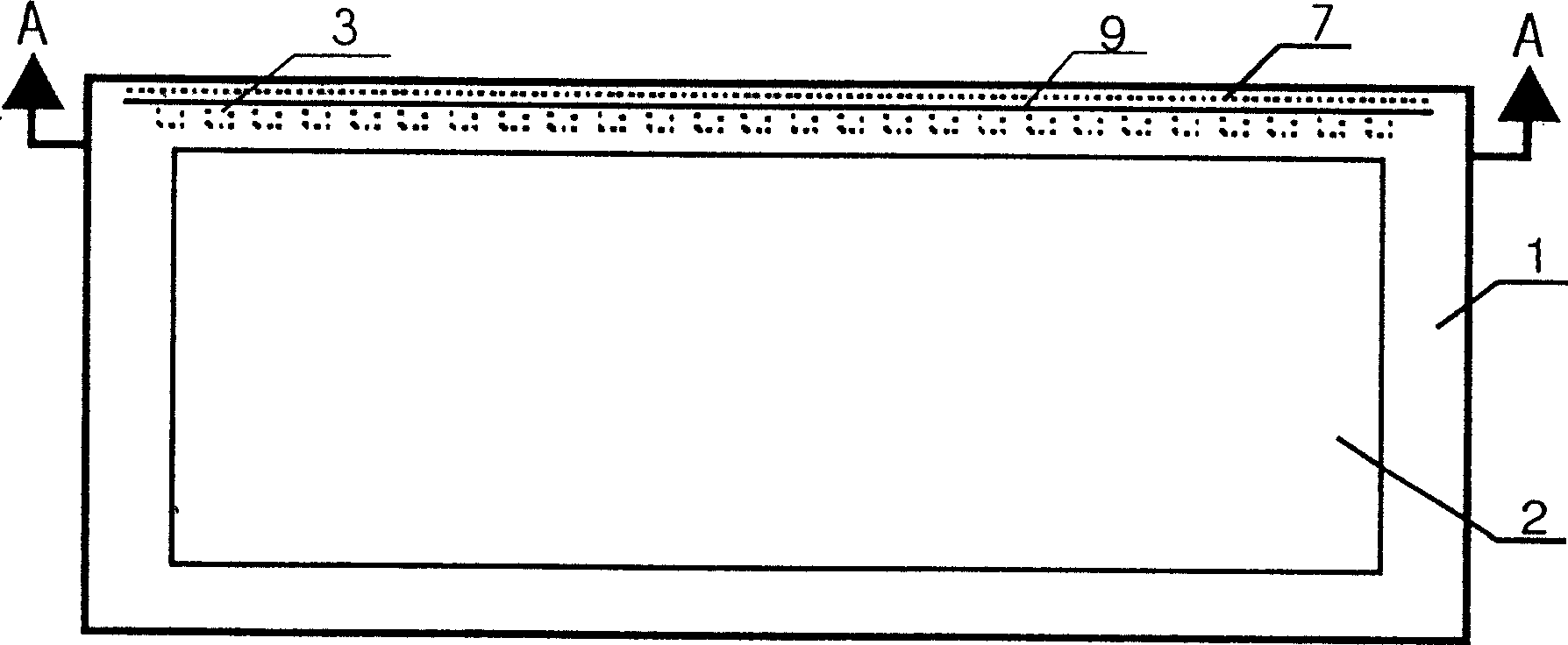
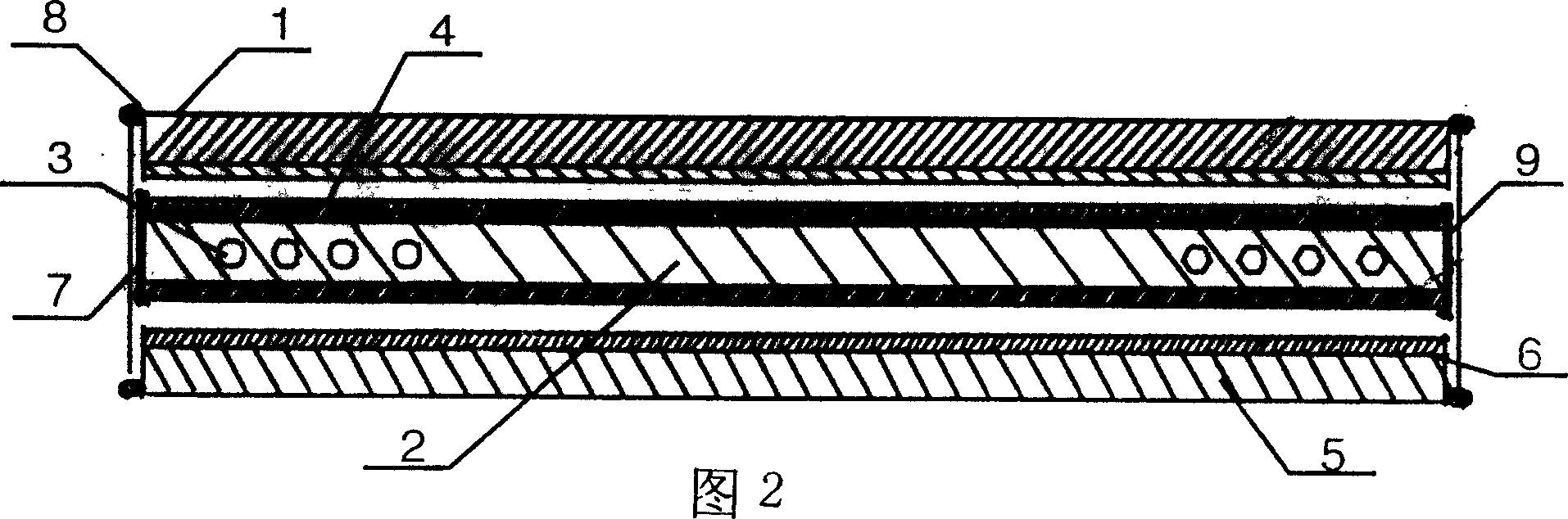
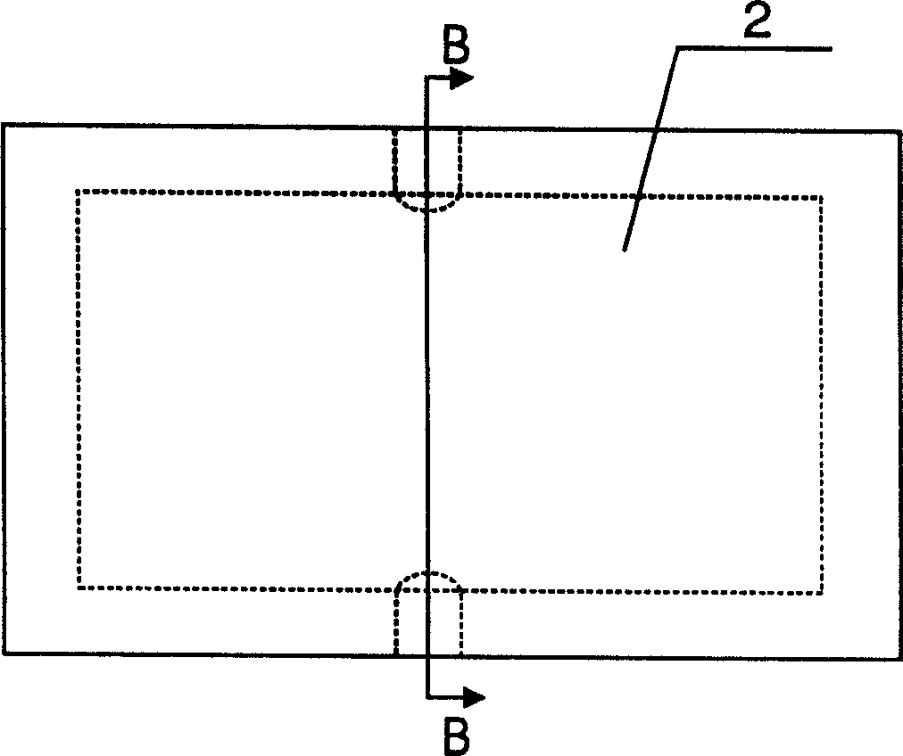
[0022] See the structure diagram Figure 1 to Figure 6 , A miniature light source "light emitting diode (LED) soft flat panel display (illumination) device". Including light source (LED or patch and current limiting protection resistor) 3, light guide plate 2, frame 1, lighting material layer 4, transparent protective plate 5, graphic carrier 6, sealing strip 7, protective plate liftable mechanism 8, printed circuit board 9. The frame 10 (such as the solid light guide plate does not need to use 10) and other components.
[0023] In one example, the surface of the light guide plate is coated (or silk-screened, sprayed, etc.) with lighting materials. After the light-emitting diodes are energized and emit light, the light passes through the light guide plate and the interface through complex optical principles such as light reflection, refraction, and diffraction, and forms on the surface of the lighting material. Soft surface light source.
[0024] In one example, the surface of the ...
PUM
 Abstract
Description
Claims
Application Information