

A heat exchanger, combination with heat exchanger and method of manufacturing the heat exchanger
A technology of heat exchangers and heat exchange devices, applied in heat exchange equipment, heat exchangers, heating methods, etc., can solve the problems that heat transfer is not well controlled and efficiency is not the highest
- Summary
- Abstract
- Description
- Claims
- Application Information
AI Technical Summary
Problems solved by technology
Method used
Image

Examples
Embodiment
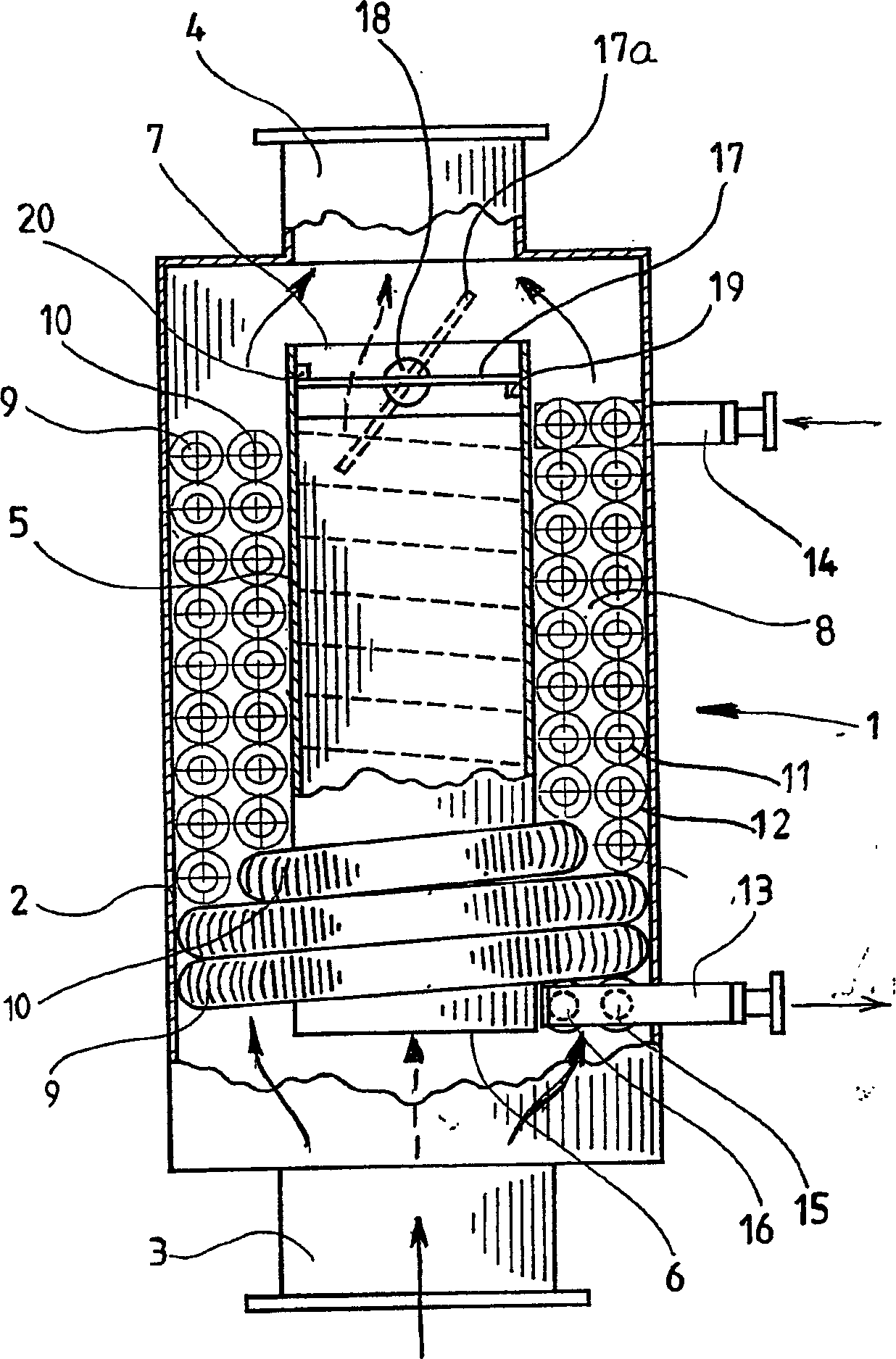
[0067] In the following, the basic technical parameters of the inventive combination of the two heat exchangers of the invention and the turbine fueled by natural gas are listed as non-limiting examples:
[0068] height, excluding entrance
1550mm
diameter, excluding insulation
633mm
insulation
100mm wrapped with galvanized steel
Exhaust gas outlet flange
DN450, DIN86044
Water In / Out Connections
Carbon steel pipe, OD 60.5x3.6mm,
2"RGW
Shell thickness (inner 5 and outer 2)
5mm
Heat exchanger weight, excluding water
475kg
Heat exchanger weight including water
500kg
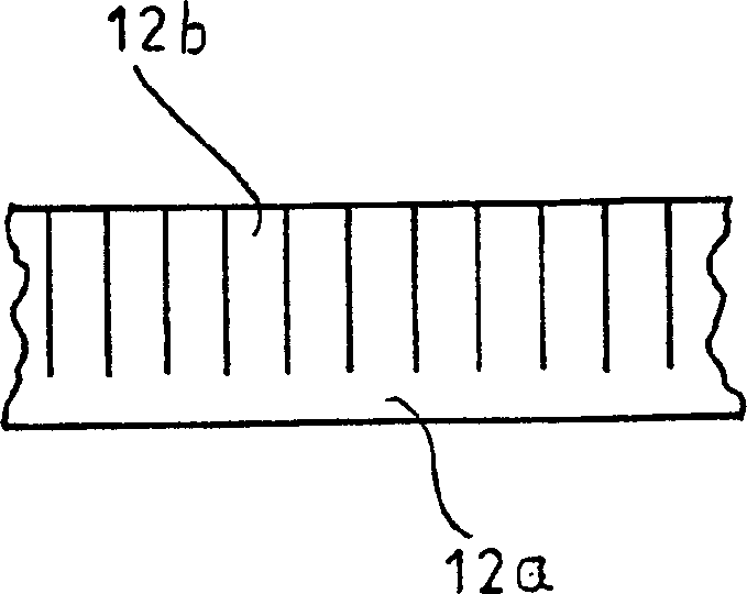
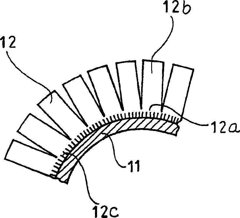
Tube 11 OD
38mm
Tube Material Thickness
3.6mm
wing type
Zigzag spirally wound wings
wing height
15mm
wing density
250pcs / m
Fin thickness
1mm
Materials, Tubes and Fins
Tube configuration
Straight forward (Inline)
...
PUM
 Abstract
Description
Claims
Application Information