DC-DC resonance converter

A resonant converter, DC-DC technology, applied in the direction of converting DC power input to DC power output, instruments, adjusting electrical variables, etc., can solve the problems of large volume, high conduction voltage drop, increase loss, etc., and achieve technical difficulties Low, small number of devices, the effect of increasing losses

Inactive Publication Date: 2017-07-18
WUHAN ZHONGYUAN ELECTRONICS GRP
View PDF6 Cites 6 Cited by
  • Summary
  • Abstract
  • Description
  • Claims
  • Application Information

AI Technical Summary

Problems solved by technology

[0022] It can be seen from the above that, when the circuit structure parameters are determined, the output voltage adjustment range is limited by the transfer function characteristic curve of the existing resonant converter, that is, the output voltage can only be adjusted by adjusting the switching frequency. When the switching frequency is high, the resonance The adjustment ability of the converter drops sharply, and the adjustment range is small, which cannot meet the wide range adjustment of the output voltage in practical applications.
[0023] Furthermore, if the output voltage adjustment range is extended, a higher switching frequency range is required, and when the switching frequency range of the resonant converter is wide, the design of the transformer and output rectification and filtering circuit is complicated. Considering the characteristics of the magnetic components in the circuit, it is necessary to follow The design of the minimum switching frequency of the circuit leads to large capacitance and inductance parameters in the transformer and filter circuit, which makes the design of the entire resonant converter complex, large in size and high in cost
[0024] Moreover, when the switching frequency is high, the on-time of the switch decreases, while the resonant period of the circuit remains unchanged. Taking the first switch on as an example, the resonant current decreases after half a resonant period. , because the time for the resonant current to decrease is not enough, there is no intersection point with the linearly increasing excitation current, the current difference between the resonant current and the excitation current is not zero, the current of the primary winding of the transformer is converted to the secondary winding of the transformer, and flows through the output rectification filter circuit The current of the rectifier diode is not zero, so that the rectifier diode is turned off when there is current flowing through it, and zero current turnoff cannot be achieved, thereby increasing the circuit loss. Further, because the rectifier diode cannot achieve zero current turnoff characteristics, As a result, the output voltage peak at both ends of the rectifier diode is very high. In order to avoid the breakdown of the rectifier diode, it is necessary to select a rectifier diode with high withstand voltage, but the conduction voltage drop of the rectifier diode with high withstand voltage is generally higher, which also increases the loss, resulting in The reliability of the converter is reduced and the efficiency is reduced
Similarly, when the first switch is turned off, the junction capacitance at both ends of the second switch needs to be discharged, so that when the voltage drop at both ends of the second switch gradually decreases to zero, zero-voltage switching of the second switch is realized, but if the switching frequency Higher, the time for discharging the junction capacitance at both ends of the second switch is not enough, so that when the voltage drop across the second switch does not drop to zero, the second switch is turned on, which also increases the circuit loss

Method used


Image

  • DC-DC resonance converter
  • DC-DC resonance converter
  • DC-DC resonance converter

Examples


Embodiment 1

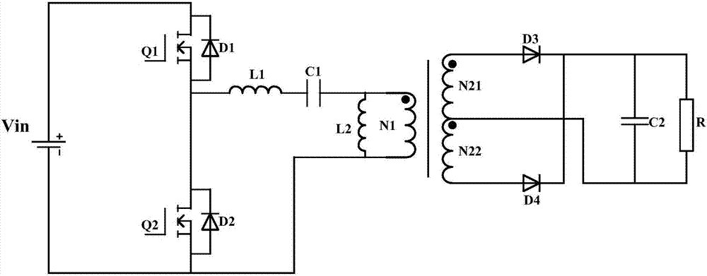
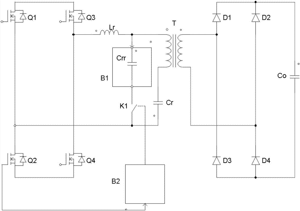
[0043] like image 3 As shown, a DC-DC resonant converter includes: full bridge switching circuit (power tube Q1, power tube Q2, power tube Q3, power tube Q4), resonant circuit (resonant inductor Lr, resonant capacitor Cr, parallel network B1 ), a transformer (T) and an output rectification filter circuit (rectifier diode D1, rectifier diode D2, rectifier diode D3, rectifier diode D4, capacitor Co).

[0044] Capacitor Crr and switch K1 are connected in series to form the first branch, and transformer T and resonant capacitor Cr are connected in series to form the second branch. After the first branch and the second branch are connected in parallel, one end is connected to the output end of the full-bridge switching circuit through the resonant inductor Lr. After the first branch and the second branch are connected in parallel, the other end is connected to the other end of the output of the full bridge switch circuit, the secondary side of the transformer T is connected to the...


PUM


Abstract

The invention discloses a DC-DC resonance converter comprising a full bridge switch circuit, a capacitor Crr and a switch K1 are connected in series to form a first branch circuit, a voltage transformer T and a resonant capacitor Cr are connected in series to form a second branch circuit, the first branch circuit and the second branch circuit are connected in parallel, one end of the first branch circuit and the second branch circuit connected in parallel is connected with an output end of the full bridge switch circuit via a resonance inductor Lr, the other end of the first branch circuit and the second branch circuit connected in parallel is connected with the other end of the full bridge switch circuit, a secondary side of the voltage transformer is connected with an output rectification filter circuit, and the DC-DC resonance converter also comprises a control network B2 which is used for measuring frequency of a PWM waveform for driving the full bridge switch circuit and controlling disconnection and connection of the control switch K1. The DC-DC resonance converter is connected in during light load time and disconnected during heavy load time, and efficiency cannot be lowered while light load voltage stability can be ensured.

Description

technical field [0001] The invention relates to the technical field of PFM power conversion, in particular to a DC-DC resonant converter, which is suitable for on-board charging of electric vehicles and power supply for other power equipment requiring high efficiency. Background technique [0002] The resonant converter is a DC / DC converter developed by using soft switching technology. By establishing a resonant circuit, the switching tube can be switched on and off at zero voltage. It has good isolation performance, low loss, and multiple output DC power supplies. Etc. [0003] figure 1 It is a schematic diagram of the circuit structure of the existing DC / DC resonant converter. Taking the DC / DC resonant converter as a half-bridge LLC resonant converter as an example, the half-bridge LLC resonant converter includes: a full-bridge switch circuit, a resonant circuit, a resonant Voltage output circuit, transformer and output rectification filter circuit, figure 1 The working...

Claims


Application Information

Patent Timeline
Patent Type & Authority Applications(China)
IPC IPC(8): H02M3/338
CPCH02M3/3381Y02B70/10
Inventor 张东华李国栋李小兵杨奇王媛
Owner WUHAN ZHONGYUAN ELECTRONICS GRP
Why Eureka
Try Eureka