Unidirectional clutch

A technology for one-way clutches and inner rings, applied in one-way clutches, clutches, automatic clutches, etc., to achieve the effects of improving versatility, no friction loss, and reducing the number of components

Inactive Publication Date: 2005-03-09
HONDA MOTOR CO LTD
View PDF0 Cites 10 Cited by
  • Summary
  • Abstract
  • Description
  • Claims
  • Application Information

AI Technical Summary

Problems solved by technology

In addition, in the absence of a neutral structure, it is necessary to reinstall the neutral structure in the gear transmission.

Method used


Image

  • Unidirectional clutch
  • Unidirectional clutch
  • Unidirectional clutch

Examples


Embodiment Construction

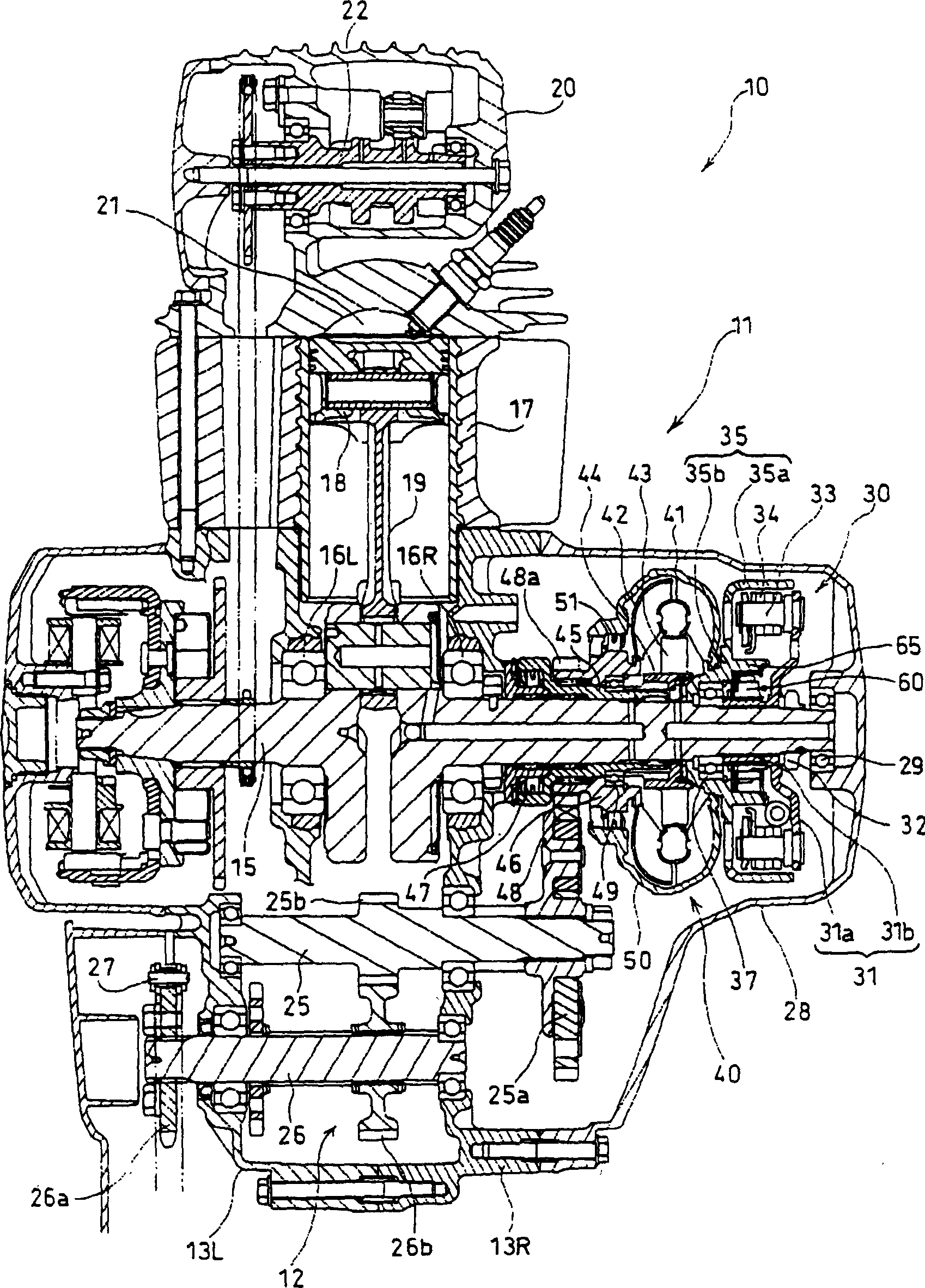
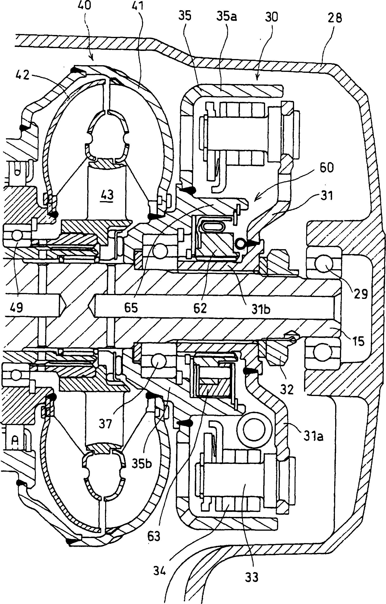
[0021] Below, the embodiment of the present invention is based on Figure 1 to Figure 9 Be explained. first, figure 1 It is a longitudinal sectional view of a power unit 10 for a motorcycle incorporating an embodiment of the one-way clutch of the present invention, figure 2 is to zoom in figure 1 Figures near the centrifugal starting clutch 30 and the one-way clutch 60 for engine braking in Fig.

[0022] The power unit 10 is constituted by an integrated internal combustion engine 11 and a load-side transmission mechanism 12 .

[0023] A crank chamber and a gear chamber are formed inside by combining the left and right halves of the left unit case 13L and the right unit case 13R, which integrate the crankcase of the internal combustion engine 11 and the gearbox of the transmission mechanism 12 .

[0024] The crankshaft 15 arranged to point to the left-right direction of the vehicle is supported by the respective left and right unit cases 13L, 13R via bearings 16L, 16R. In...


PUM


Abstract

To improve a one-way clutch incorporated into an engine of a motorcycle to eliminate the need for switching a gear to a neutral position in the case of push walk of vehicle. A one-way clutch 60 comprises a clutch inner wheel 62, a clutch outer wheel 65 coaxial with the clutch inner wheel 62, a cam surface 62b formed on the inner periphery of the clutch outer wheel 65, a roller (rolling member) 64 arranged between the clutch inner wheel 62 and the clutch outer wheel 65 and rolling on the cam surface 62b, and a compression spring (biasing member) 66 biasing in a direction of narrowing the roller 64 by pressure of the clutch inner wheel 62 and the clutch outer wheel 65 along the circumferential direction. The clutch is characterized by comprising an centrifugal weight (restricting member) 63 which restricts, in low-speed rotation, the movement of the roller 64 in the biasing direction within the range where the roller 64 can freely roll, and releases the restriction in the case of a predetermined number of rotation or more.

Description

technical field [0001] The present invention relates to a one-way clutch, for example, relates to a one-way clutch for engine braking which is installed in an engine of a motorcycle. Background technique [0002] In such a motorcycle engine, conventionally, there is a structure in which a one-way clutch that only allows transmission of power from the automatic starter to the crankshaft side is provided on the crankshaft (for example, refer to Patent Document 1 or Patent Document 2). ). [0003] [Patent Document 1] Publication of Publication No. 59-116639 [0004] [Patent Document 2] JP-A-62-75141 [0005] The conventional one-way clutch described above always operates as a one-way clutch. Therefore, when such a one-way clutch is used as an engine brake to allow only power transmission from the wheel side to the crankshaft side, even if the engine stops, the rotation of the wheels is transmitted to the crankshaft. Therefore, when the engine is stopped, when the vehicle is...

Claims


Application Information

Patent Timeline
Patent Type & Authority Applications(China)
IPC IPC(8): F16D43/16F02B61/00F16D41/06F16D43/00
CPCF16D43/18F16D2043/145F16D41/064
Inventor 阿部克哉黑岩保行近藤仁
Owner HONDA MOTOR CO LTD
Why Eureka
Try Eureka