Condenser

A condenser and subcooling technology, applied in subcoolers, evaporators/condensers, refrigerators, etc., can solve the problems of performance degradation of heat exchangers, increase of power consumption, and reduction of two-phase zones, and achieve good performance. Heat transfer performance, effect of improved subcooling

Inactive Publication Date: 2005-03-09
LG ELECTRONICS INC
View PDF0 Cites 11 Cited by
  • Summary
  • Abstract
  • Description
  • Claims
  • Application Information

AI Technical Summary

Problems solved by technology

[0023] Thus, as pointed out above, although the liquid in the supercooled liquid region has a slower flow rate and lower thermal conductivity, it is only one-tenth as strong as the two-phase region, so that the liquid in the supercooled liquid region does not have to be dispersed , but these liquids are output from each pipe, thereby increasing the liquid (or subcooled) region and thereby reducing the two-phase region with good thermal conductivity
Therefore, a heat exchanger of a given size results in a decrease in performance and an increase in electrical power consumption

Method used


Image

  • Condenser
  • Condenser
  • Condenser

Examples


Embodiment Construction

[0038] The following detailed description will describe a condenser according to a preferred embodiment of the present invention with reference to the accompanying drawings.

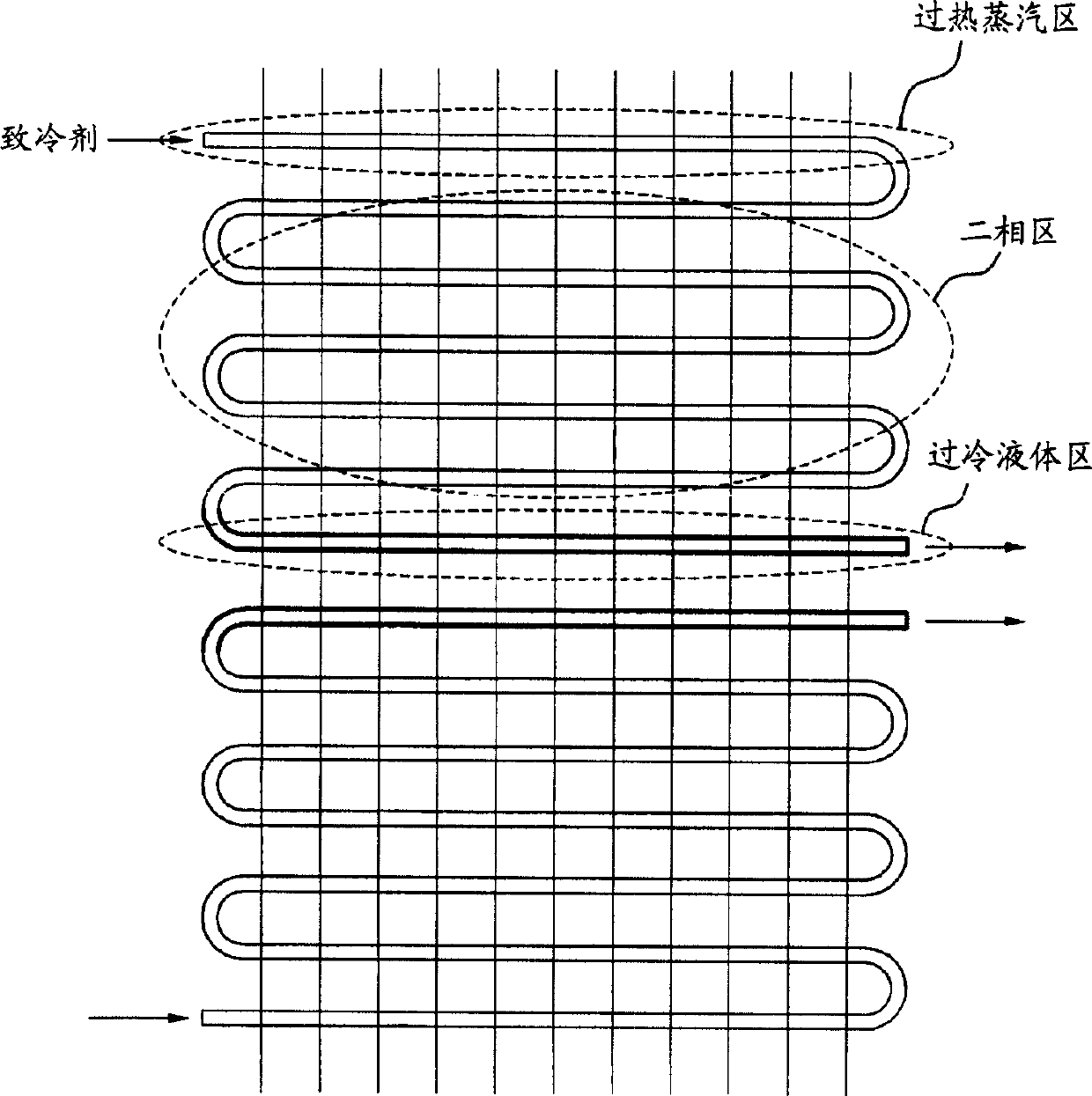
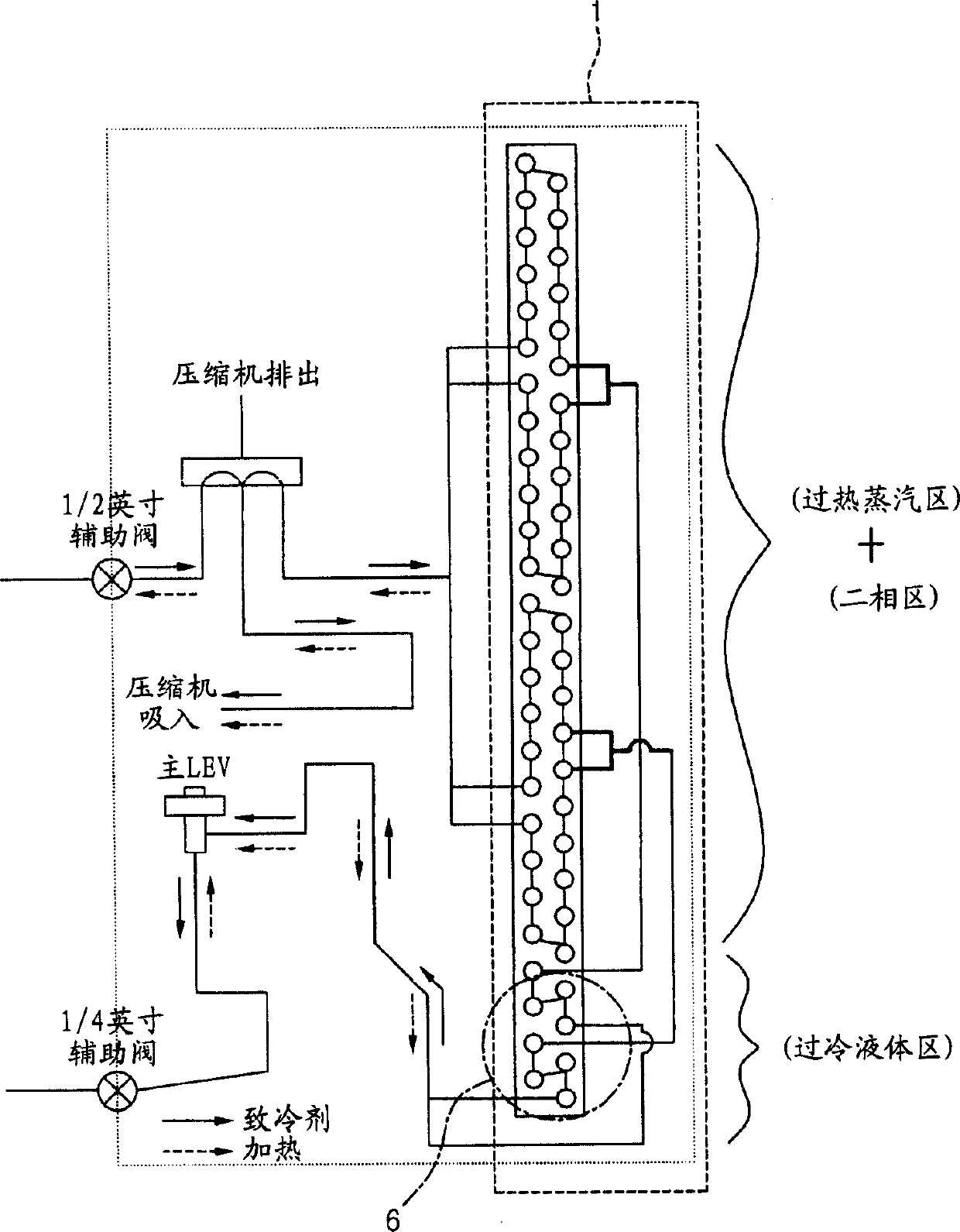
[0039] Fig. 3 is a block diagram schematically representing a structure comprising a condenser according to the present invention, Fig. 4a and 4b represent the state of the refrigerant in the condenser, the path and area through which the refrigerant passes, and Fig. 5 are graphs and tables showing the relationship between subcooled tubes and coefficients of performance.

[0040] First, an introduction will be made with reference to FIG. 3 .

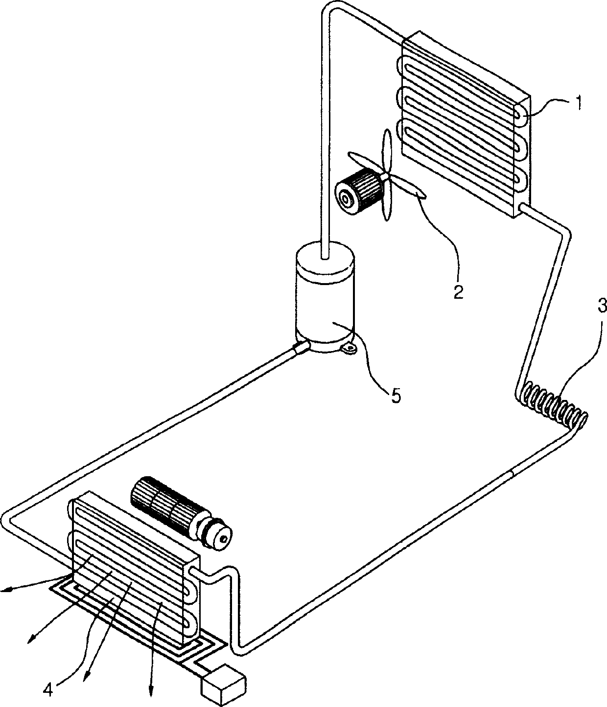
[0041] Refrigerant output from an indoor unit (not shown) is branched into one or more paths through an auxiliary valve and a discharge valve of the compressor, and then input to the condenser 1 .

[0042] The bifurcated path of the present invention passes through the tubes of the superheated vapor zone and the two-phase zone and merges into one tube of the subco...


PUM


Abstract

A condenser where a refrigerant introduced from a compressor is coexisting in super-heated vapor, two-phase and super-cooled liquid states combines a plurality of refrigerant pa ths within at least one of super-heated vapor and two-phase regions to output the refrigerant to the super-cooled liquid region, and provides a proper percentage of the super-cooled liq uid region.

Description

technical field [0001] The present invention relates to a condenser, and more particularly, to a method for supplying subcooled liquid to a subcooled liquid zone by combining a plurality of refrigerant lines on at least one of the superheated vapor zone and the two-phase zone in the condenser. A condenser that outputs refrigerant and provides an appropriate percentage of the subcooled liquid zone where the refrigerant exiting the compressor exists simultaneously in a superheated vapor state, a two-phase state and a subcooled liquid state. Background technique [0002] Generally speaking, the compression refrigeration cycle is completed by a compressor 5 , a condenser 1 , an expansion valve 3 and an evaporator 4 . At present, there is a strong focus on the need to minimize the power consumption in air conditioners comprising such a compression refrigeration cycle. [0003] Accordingly, various research programs including improvement of respective performances of main compone...

Claims


Application Information

Patent Timeline
Patent Type & Authority Applications(China)
IPC IPC(8): F25B39/04F25B40/02
CPCF25B40/02F25B39/04
Inventor 洪起洙陈深元文栋洙
Owner LG ELECTRONICS INC
Why Eureka
Try Eureka