Reciprocating motor

A motor and reciprocating technology, applied in electric components, reciprocating/swinging/vibrating magnetic circuit components, electromechanical devices, etc., can solve problems such as difficulty in ensuring the roundness of the magnet frame, deformation of the slit, and reduction in molding accuracy

Inactive Publication Date: 2005-03-09
LG ELECTRONICS INC
View PDF0 Cites 4 Cited by
  • Summary
  • Abstract
  • Description
  • Claims
  • Application Information

AI Technical Summary

Problems solved by technology

[0014] However, in such conventional reciprocating motors, the slits formed in order to weaken the eddy current loss generated during the operation of the motor are formed in a strip shape with a narrow width, and thus there is a problem that since the slits are formed during the molding process, Deformation due to compressive stress generated in the circumferential direction of the magnet holder reduces molding accuracy and makes it difficult to ensure the roundness of the magnet holder
Since the width of the slit is narrow and thin, the punch used to perform the punching operation should also be narrow and thin, which brings about the problem that the punch and die are easily damaged during work

Method used


Image

  • Reciprocating motor
  • Reciprocating motor
  • Reciprocating motor

Examples


Embodiment Construction

[0032] Hereinafter, embodiments of a reciprocating motor according to the present invention will be described with reference to the accompanying drawings.

[0033] There are various embodiments of the reciprocating motor according to the present invention, therefore, only preferred embodiments will be described below.

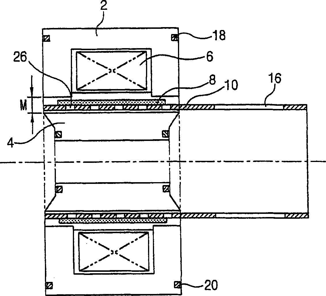
[0034] image 3 is a sectional view showing a reciprocating motor according to the present invention.

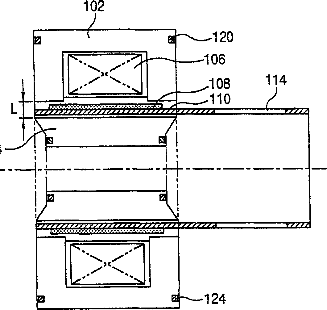
[0035] The reciprocating motor according to the present invention includes: a cylindrical outer stator 2, which is fixed to a housing (not shown in the figure); an inner stator 4, which is positioned on the outer stator 2 with a predetermined air gap M inner peripheral surface, and can form a magnetic flux between itself and the outer stator 2; a coil 6, which is either wound on the outer stator 2, or is wound on the inner stator 4; a magnet 8, which is positioned to be able to Perform linear motion between the outer stator 2 and the inner stator 4; and a m...


PUM


Abstract

A reciprocating motor in which a plurality of eddy current preventing holes ( 26 ) are formed in the directions of circumference and shaft of a magnet frame ( 10 ) in a magnet mounting portion ( 12 ) of the magnet frame ( 10 )connected between the magnet ( 8 )and component part which will perform a reciprocating movement, for transmitting a reciprocating movement of the magnet ( 8 ) to a component part, to prevent deformation of the magnet frame (10)in molding the eddy current ( 26 ) and maintain roundness of the magnet frame precisely by improving the structure of the eddy current preventing holes which are molded in the magnet frame.

Description

technical field [0001] The present invention relates to a reciprocating motor, in particular to such a reciprocating motor: it can minimize the eddy current loss generated when the motor is working and prolong the working life of the motor. Background technique [0002] In general, motors are classified into rotary motors that convert electrical energy into rotary motion, reciprocating motors that convert electrical energy into reciprocating linear motion, and the like. [0003] Specifically, in the reciprocating motor, an outer stator and an inner stator are positioned to be spaced apart from each other by a predetermined gap, and a rotor with magnets is disposed between the outer stator and the inner stator. When electricity is applied to the coils wound on the stator, the rotor is reciprocated by the interaction between the stator and the magnets. Reciprocating motors are commonly used on reciprocating compressors. [0004] figure 1 is a sectional view showing a conven...

Claims


Application Information

Patent Timeline
Patent Type & Authority Applications(China)
IPC IPC(8): H02K41/02H02K1/27H02K1/34H02K33/16
CPCH02K1/34H02K33/16H02K41/02
Inventor 郑圆铉具本哲
Owner LG ELECTRONICS INC
Why Eureka
Try Eureka