Display driver, electro-optical device, and control method for display driver

A technology of display driver and driving part, which is applied to identification devices, static indicators, cathode ray tube indicators, etc., can solve the problems of inability to seek chip size, shrinkage, and power consumption reduction, and achieve miniaturized power consumption and low power consumption. Power, effect of simplified composition

Inactive Publication Date: 2005-03-16
SEIKO EPSON CORP
View PDF0 Cites 5 Cited by
  • Summary
  • Abstract
  • Description
  • Claims
  • Application Information

AI Technical Summary

Problems solved by technology

[0006] However, there is a problem in the above-mentioned data driver that a signal input terminal for identifying one of the command data and the display data is required.
Therefore, further reduction in chip size and reduction in power consumption cannot be sought

Method used


Image

  • Display driver, electro-optical device, and control method for display driver
  • Display driver, electro-optical device, and control method for display driver
  • Display driver, electro-optical device, and control method for display driver

Examples


Embodiment Construction

[0044] Hereinafter, preferred embodiments of the present invention will be described in detail with reference to the accompanying drawings. The embodiments described below do not limit the protection scope of the present invention, and the components described below are not all essential components of the present invention.

[0045] 1. Overview of the display driver in this embodiment

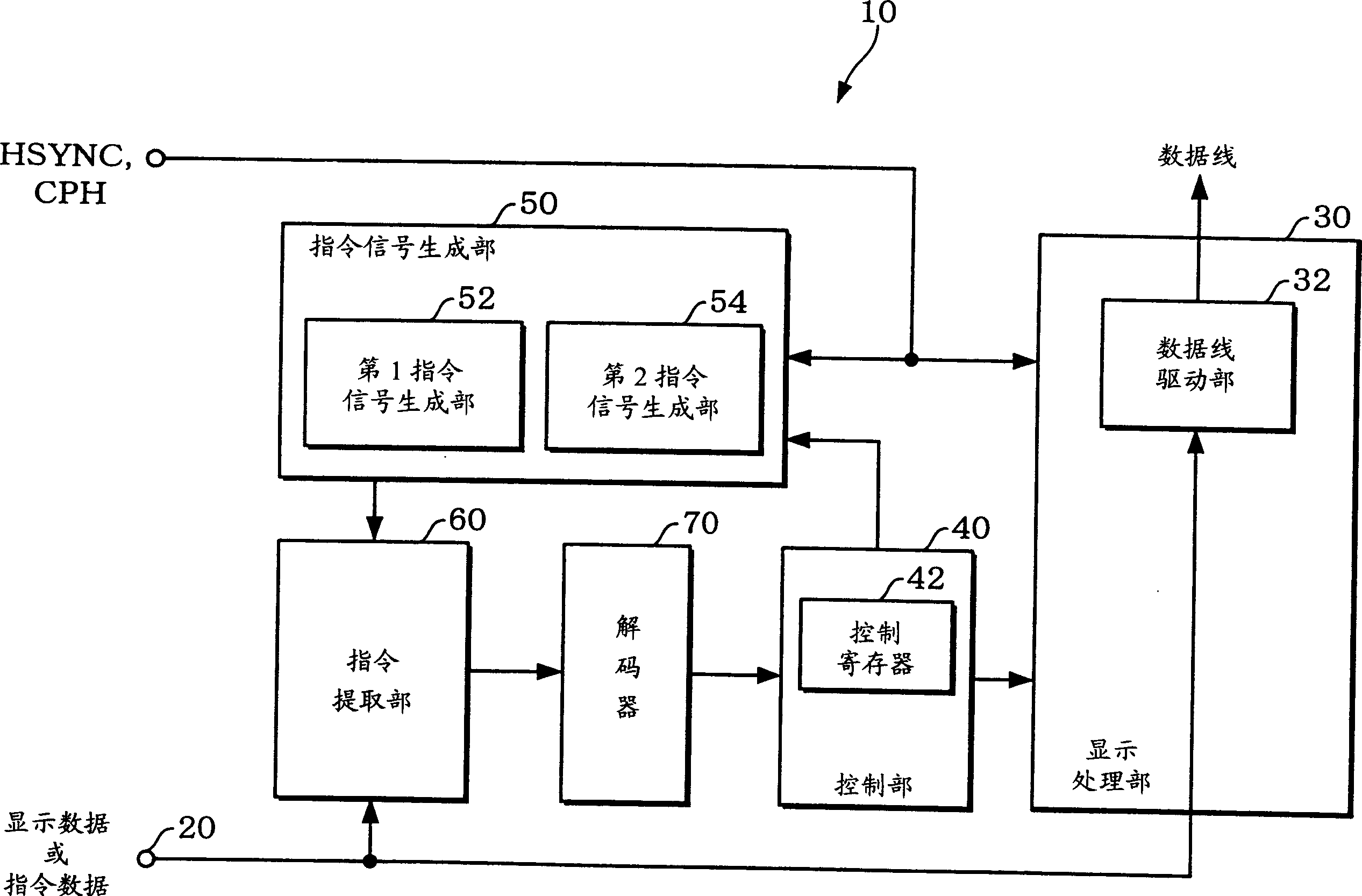
[0046] figure 1 A schematic block diagram showing the configuration of the display driver in this embodiment is shown in .

[0047] The display driver 10 in this embodiment includes a data input unit 20 , a display processing unit 30 , a control unit 40 , a command signal generation unit 50 , a command extraction unit 60 , and a decoder 70 .

[0048] Display data or command data is input to the data input unit 20 . The input data input to the data input unit 20 is time-divided into display data and command data. The function of the data input unit 20 is realized by a data input terminal, or...


PUM


Abstract

A display driver includes: a data input section to which display data or command data is input; a display processing section which includes a data line driver section driving the data lines based on the display data input through the data input section; a control register for controlling the display processing section; a command signal generation section which generates a command signal which changes at a predetermined timing and is used to identify the command data; a command extraction section which extracts the command data from data such as the display data input through the data input section based on the command signal; and a decoder which decodes the command data extracted by the command extraction section. A value corresponding to a decoding result of the command data is set in the control register. The display processing section is controlled based on the value set in the control register.

Description

technical field [0001] The invention relates to a display driver, an electro-optical device and a control method of the display driver. Background technique [0002] A display panel represented by an electro-optical panel includes a plurality of scanning lines and a plurality of data lines, and pixels are defined according to the scanning lines and data lines. The scan driver sequentially selects a plurality of scan lines. A plurality of data lines are driven by a data driver (display driver) according to display data. The scan driver and the data driver are controlled by the display controller. [0003] Generally speaking, the data driver performs driving control corresponding to the command set by the display controller. There are many known techniques of data drivers for such command setting drive control. [0004] For example, a certain data driver adopts a configuration in which command address data is input as one data, and command data and display data are input a...

Claims


Application Information

Patent Timeline
Patent Type & Authority Applications(China)
IPC IPC(8): G02F1/133G09G3/20G09G3/36G09G5/00
CPCG09G2310/0251G09G2310/027G09G3/3688G09G5/006G09G3/3648
Inventor 森田晶
Owner SEIKO EPSON CORP
Why Eureka
Try Eureka