Controllable silicon triggering circuit for equipotential switching of capacitor

A trigger circuit and equipotential technology, applied in electronic switches, electrical components, harmonic reduction devices, etc., can solve problems such as the ability of optocouplers to withstand voltage, and achieve the effect of avoiding inrush current

Inactive Publication Date: 2005-03-16
SHANGHAI JIAO TONG UNIV +1
View PDF0 Cites 6 Cited by
  • Summary
  • Abstract
  • Description
  • Claims
  • Application Information

AI Technical Summary

Problems solved by technology

[0004] However, this solution not only has the problem of fast switching capacitors, but also the withstand voltage of the optocoupler triggered by zero crossing is only 400V, and when the system voltage is 380V AC effective value, the peak value of the power supply voltage is 537V, the above optocoupler There is a problem with the ability to withstand voltage, so both aspects require the redesign of the zero-crossing trigger circuit

Method used


Image

  • Controllable silicon triggering circuit for equipotential switching of capacitor

Examples


Embodiment Construction

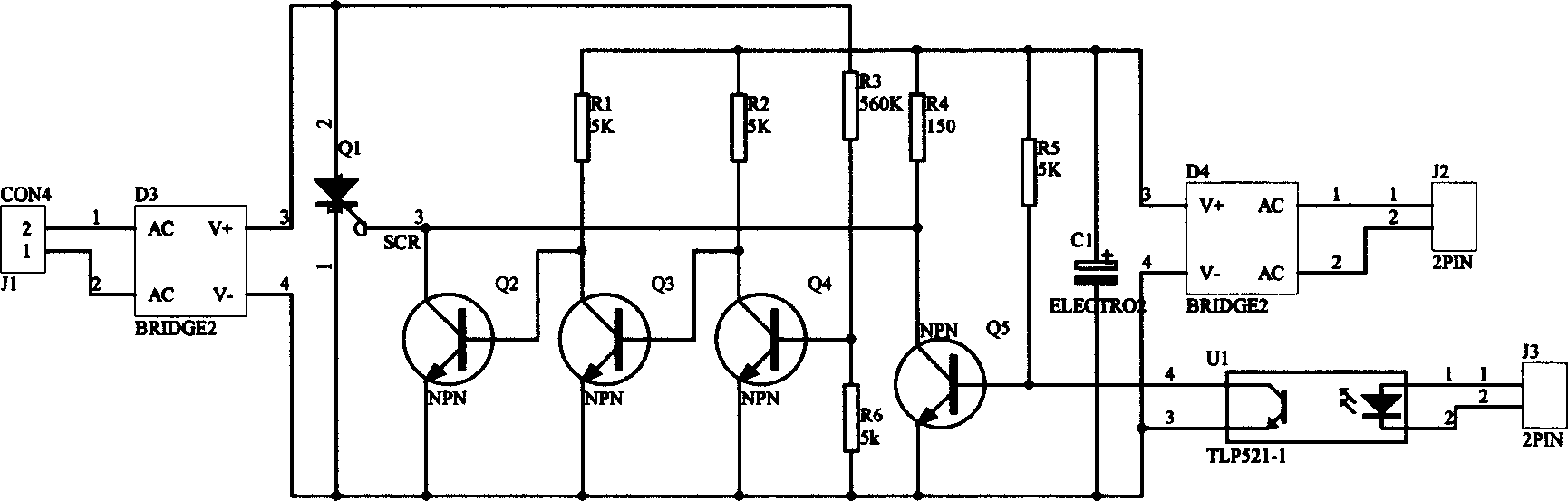
[0013] The technical solutions of the present invention will be further described below with reference to the accompanying drawings.

[0014] The principle diagram of the capacitor equipotential switching thyristor trigger circuit designed by the present invention is as follows: figure 1 shown. The auxiliary power supply is the AC voltage that meets the requirements from the grid voltage through the transformer, and then the DC voltage obtained by the auxiliary power supply rectifier bridge D4 and capacitor C1 filtering. The low potential of this DC voltage is connected to the common terminal, and the high potential is connected to the base and collector of the trigger current control transistor Q5 through resistors R5 and R4, respectively, and the amplifier transistor Q3 and the voltage zero-crossing detection transistor Q4 are respectively connected through resistors R1 and R2. The collector of the trigger current control transistor Q5, the amplifying transistor Q3 and the ...


PUM


Abstract

The invention is a capacitance equipotential-switching thyristor triggering circuit, including high- voltage thyristor, control optical coupler and auxiliary power supply, and adopting trigger current control triode, amplifier triode, voltage zero-passage detecting triode and trigger current by-pass triode. Its main circuit voltage is rectified and then applied on two ends of the high-voltage thyristor, the auxiliary power supply is a DC power supply derived from rectification and filtration of an AC power supply and applied on to a resistance connected with the collector of trigger current control triode so as to generate a trigger current for the high-voltage thyristor, and the high-voltage thyristor is triggered as the two conditions that the control optical coupler is switched on and that the main circuit voltage passes zero. It realizes the function of triggering by zero passage of the main circuit voltage at high voltage, needs no connection waiting time, and realizes the equipotential capacitance switching, and avoids the impact current as the capacitance is connected to the electric network.

Description

technical field [0001] The invention relates to a capacitor equipotential switching thyristor trigger circuit, which is used for switching control of capacitors in an alternating current circuit. The invention belongs to the technical field of voltage zero-crossing triggering of thyristors. Background technique [0002] There are often requirements for switching capacitors in active filtering and reactive power compensation equipment. If the residual voltage on the capacitor is not equal to the system voltage, there will be a large inrush current. Therefore, it is required to connect the capacitor to the grid when the grid voltage crosses zero, so that the inrush current can be avoided when the capacitor is connected to the grid. The principle of the method currently used is to first make the voltage on the capacitor equal to zero, and control the switch to connect the capacitor to the grid when the grid voltage crosses zero. In this way, the grid voltage does not generate...

Claims


Application Information

Patent Timeline
Patent Type & Authority Applications(China)
IPC IPC(8): H02J3/01H02J3/18H03K17/13
CPCY02E40/30Y02E40/40
Inventor 常越姜宁陈刚陈伟王春宁李长益杨爱华
Owner SHANGHAI JIAO TONG UNIV
Why Eureka
Try Eureka