Cavity adjusting method for laser gyro and used light path and path length control mirror

A technology of laser gyro and control mirror, which is applied in the field of high-precision cavity adjustment, which can solve the problems of closed-loop resonant cavity difference, large internal and external pressure difference, and deformation of reflective mirrors, etc., to achieve reliable operation, short cavity adjustment time, and high precision. Effect

Active Publication Date: 2005-04-06
NAT UNIV OF DEFENSE TECH
View PDF0 Cites 6 Cited by
  • Summary
  • Abstract
  • Description
  • Claims
  • Application Information

AI Technical Summary

Problems solved by technology

However, the benchmark of this traditional cavity tuning method is to introduce reference light from the outside to tune the cavity. The state of the cavity body during cavity tuning is significantly different from the actual working state of the laser gyro filled with working gas when the gain medium is in an excited state. , which inevitably has many disadvantages: 1. When adjusting the cavity, the reference light input to the gyro cavity may not be completely coaxial with the optical path hole of the cavity, resulting in deviation
2. The cavity adjustment process is carried out in the atmospheric environment, and when the active cavity laser gyro is in the actual working state, the cavity is at low pressure, so the pressure difference between the inside and outside of the lens in the actual working state is different from the inside and outside pressure difference when the cavity is adjusted Larger (the difference between the two is about 1atm), which will cause the slight deformation of the reflective mirror (mainly the cavity length control mirror with a thin bottom structure), so that the reflection points on the mirror in the loop and the reflection points when adjusting the cavity inconsistent
3. The cavity adjustment process is carried out for a passive cavity that is not filled with working gas, and it is impossible to involve the gain characteristics of the gain section in the actual working state, so there are actual differences between the closed-loop resonators of the two
The three gyroscopes are intertwined with each other, it is difficult to achieve the best reflector position through limited manual adjustment, and the optical paths of the three laser gyroscopes cannot be in a relatively ideal closed loop at the same time

Method used


Image

  • Cavity adjusting method for laser gyro and used light path and path length control mirror
  • Cavity adjusting method for laser gyro and used light path and path length control mirror
  • Cavity adjusting method for laser gyro and used light path and path length control mirror

Examples


Embodiment Construction

[0016] The structure of the optical path length control mirror of the present invention and the method for adjusting the cavity by using it will be further described below in conjunction with the accompanying drawings and an embodiment of cavity tuning by scanning an orthogonal three-axis laser gyroscope.

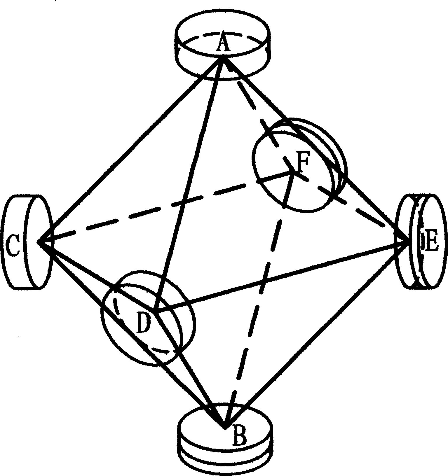
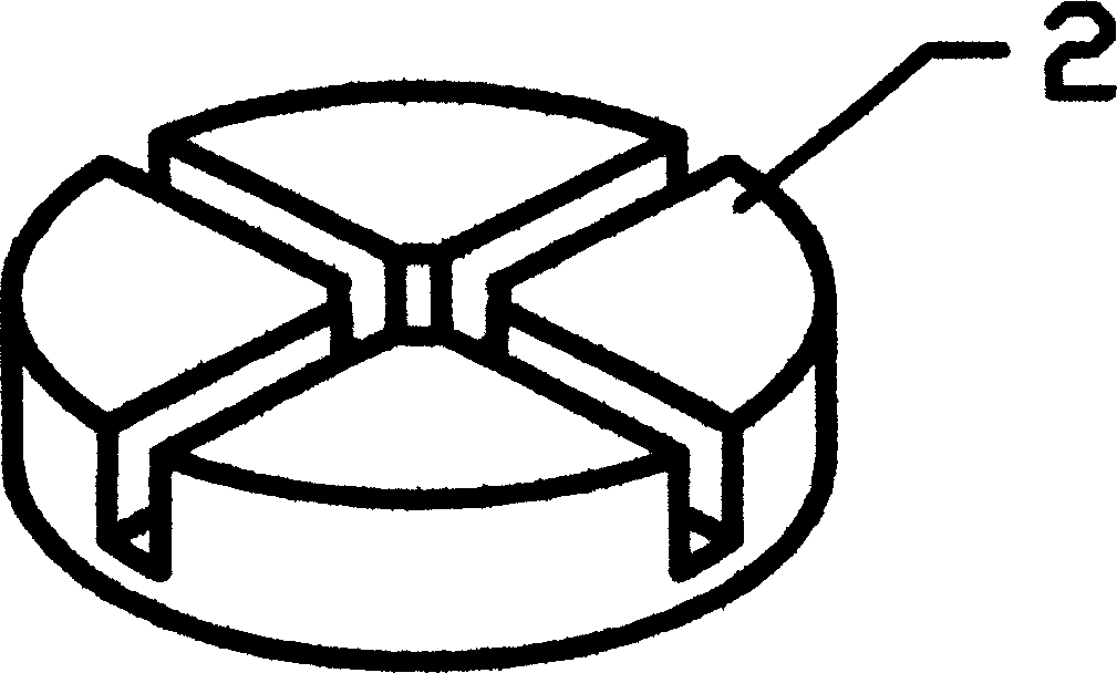
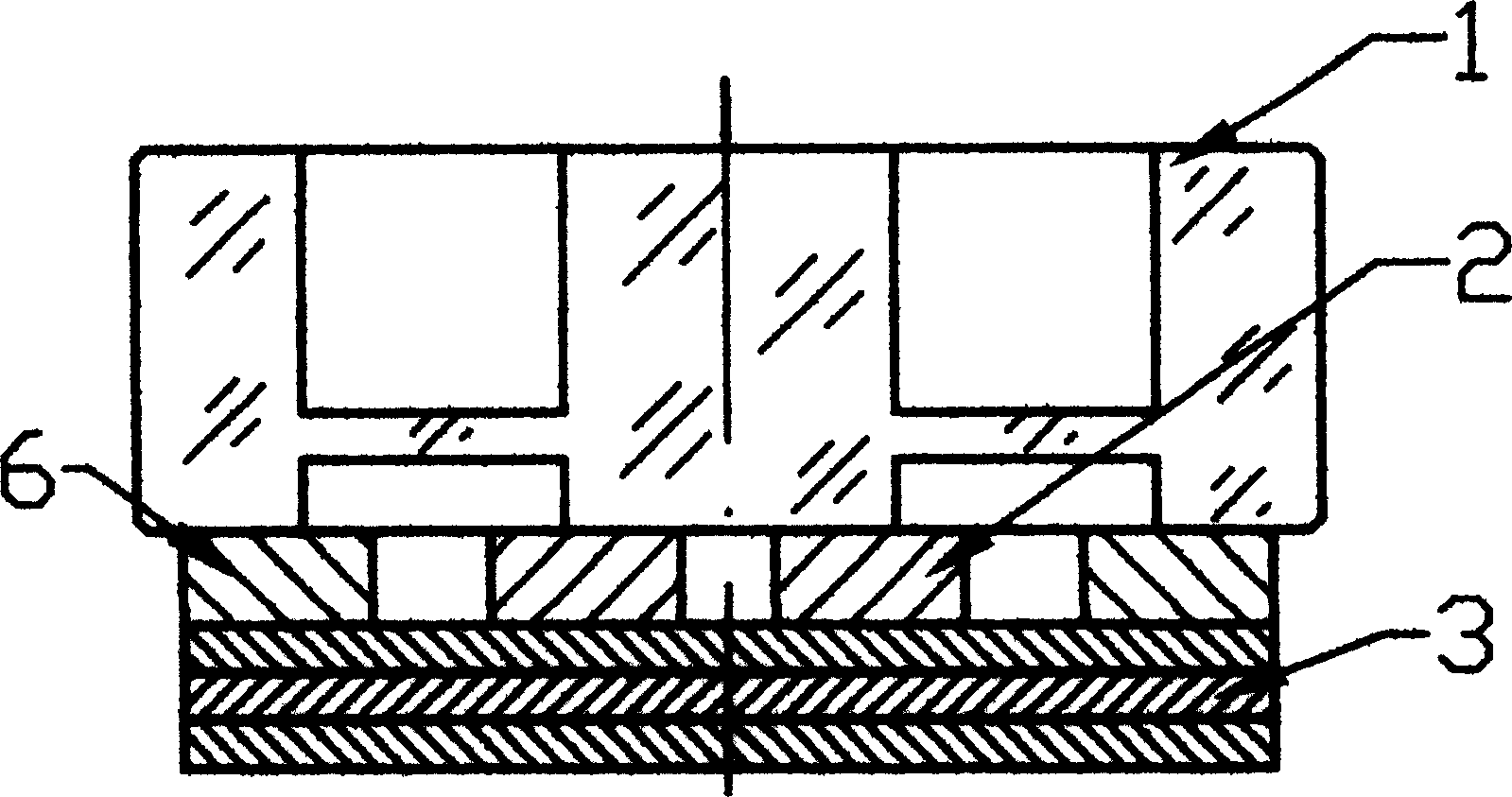
[0017] Such as figure 1 As shown, three mutually orthogonal annular light paths share six reflectors, wherein reflectors A, C, and D are output mirrors, and reflectors B, E, and F are optical path length control mirrors designed by the present invention (or process long angle control mirror), each mirror is used by two loops at the same time. The optical path length control mirror structure designed by the present invention is as follows image 3 As shown, the slot 1 is made of fused silica or glass-ceramic material, and its spherical mirror surface is on the central column, and the central column is relatively easy to produce translation or deflection relative to the oute...


PUM


Abstract

This invention discloses a laser gyroscope chamber adjusting method and its light path distance control lens. The method is the following: to exert toothed wave voltage on four control units of the angle control elements; to whole scan loop light path in two-dimensional space, wherein, two control units in one group are of same frequency and reverse voltage; the maximum scanning voltage of the output light intensity is the chamber voltage of the best loop resonance light path. The light path distance control lens comprises slotted vane , angle control element , matching loop and distance control element.

Description

technical field [0001] The invention relates to high-precision cavity tuning of an active cavity laser gyro, in particular to high-precision cavity tuning of a highly integrated three-axis laser gyro sharing six mirrors. Background technique [0002] The cavity adjustment of the laser gyro is to adjust the reflection direction of several (three or more) mirrors forming a circular loop to make it a closed-loop resonant cavity with maximum gain and minimum loss. The traditional cavity adjustment method is to use reference light to assist cavity adjustment. It usually uses the different reflection directions of different points on the spherical mirror to control the optical path, so that the reference light forms resonance in the gyro cavity to achieve the purpose of cavity adjustment. However, the benchmark of this traditional cavity tuning method is to introduce reference light from the outside to tune the cavity. The state of the cavity body during cavity tuning is significa...

Claims


Application Information

Patent Timeline
Patent Type & Authority Applications(China)
IPC IPC(8): G01C19/64G01C25/00
Inventor 金世龙
Owner NAT UNIV OF DEFENSE TECH
Why Eureka
Try Eureka