Motion control and vibration control experimental system for flexible cantilever beam in noninertial system

A flexible cantilever and motion control technology, applied in the field of mechanical engineering, can solve problems such as the inability to realize the active control of vibration, the inability to realize the motion control and precise positioning of the flexible beam, and the inability to apply the experimental research of the rotating flexible beam.

Inactive Publication Date: 2005-04-06
SHANGHAI JIAO TONG UNIV
View PDF0 Cites 23 Cited by
  • Summary
  • Abstract
  • Description
  • Claims
  • Application Information

AI Technical Summary

Problems solved by technology

However, this experimental device cannot meet the requirements of the current theoretical research on the motion control and vibration control of the rotating flexible cantilever beam: there is no actuating device on the flexible beam, and the active control of vibration cannot be realized; the rotational motion of the star part of the air bearing platform is not affected The control of the feedback channel cannot realize the motion control and precise positioning of the flexible beam; the whole system works under low-speed conditions, and cannot be applied to the experimental research of high-speed, high-acceleration rotating flexible beams

Method used


Image

  • Motion control and vibration control experimental system for flexible cantilever beam in noninertial system
  • Motion control and vibration control experimental system for flexible cantilever beam in noninertial system
  • Motion control and vibration control experimental system for flexible cantilever beam in noninertial system

Examples


Embodiment Construction

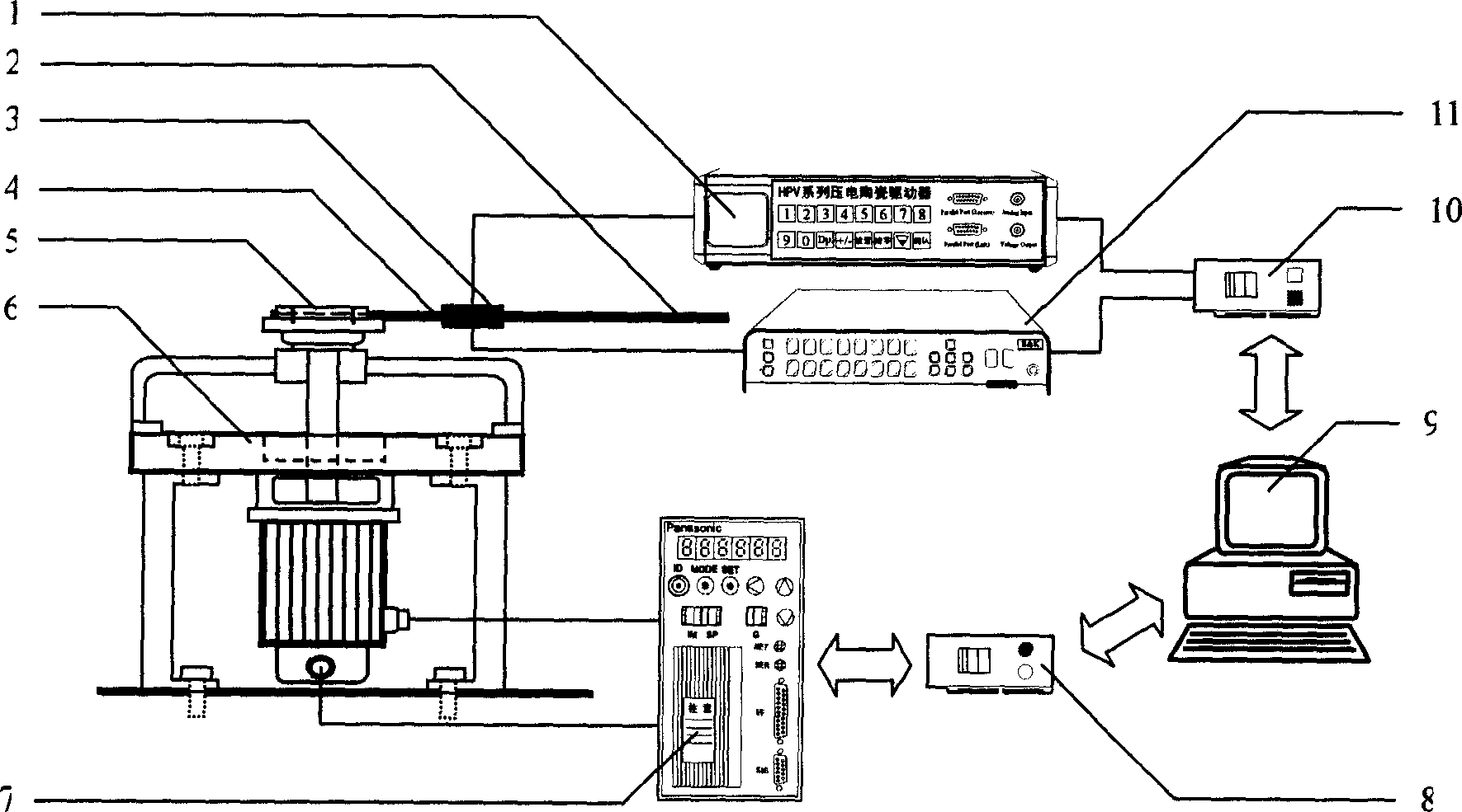
[0013] Such as figure 1 As shown, the present invention includes: a high-voltage power amplifier 1, an aluminum beam 2, a piezoelectric actuator 3, a piezoelectric sensor 4, a fixture 5, a high-speed rotating test bench 6, a motor driver 7, and a motor motion control card 8 based on a PCI bus , computer 9, DSP control card 10 and signal conditioning amplifier 11 based on PCI bus. The piezoelectric sensor 4 and the piezoelectric actuator 3 are pasted on the aluminum beam 2, and are set on the high-speed rotating test bench 6 through the fixture 5. The analog output terminal of the DSP control card 10 is connected to the analog input terminal of the high-voltage power amplifier 1, and the high-voltage power The voltage output terminal of the amplifier 1 is connected to the electrode of the piezoelectric actuator 3, the electrode of the piezoelectric sensor 4 is connected to the analog input terminal of the DSP control card 10 through the signal conditioning amplifier 11, and the...


PUM


Abstract

It is a non-inertial frame flexible cantilever beam movement control and vibration control test system, wherein, its aluminium beam is attached with piezo-sensor and piezo-actuator which are fixed on the high-speed rotation test bench though clamper. The analog output end of DSP control card is connected with analog input end of high-pressure power amplifier. The voltage output of high-pressure power amplifier is connected with electrode of piezo-actuator. The piezo-sensor electrode is connected with the analog input end of DSP control card through signal adjusting amplifier. The coder of motor driver is connected with the high-speed rotation test bench. The DSP control card and motor movement control card are plugged in the IO extension tank of computer.

Description

technical field [0001] The invention relates to a motion control and vibration control experiment system, in particular to a motion control and vibration control experiment system of a flexible cantilever beam in a non-inertial system, which is used in the field of mechanical engineering. Background technique [0002] In the process of developing the prototype system of the key technical unit of IC post-packaging equipment, the mechanical model of the rotating flexible cantilever beam was abstracted. Due to the specific characteristics of the IC industry, the positioning accuracy of the rotating flexible beam is required to be less than 5 μm, and it is required to rotate at high speed and high speed. Vibration active control is implemented under acceleration start-stop conditions. [0003] The motion control and vibration control experimental system based on high-speed and high-acceleration rotating flexible cantilever beams can reveal new mechanical phenomena of key technol...

Claims


Application Information

Patent Timeline
Patent Type & Authority Applications(China)
IPC IPC(8): G01M7/02
Inventor 孟光周烁吕万明李鸿光
Owner SHANGHAI JIAO TONG UNIV
Why Eureka
Try Eureka