Gripper used for semiconductor laser chamber surface filming and bar loading device

A laser and semiconductor technology, applied in the structure of optical resonator cavity, clamps, manufacturing tools, etc., can solve the problems of laser bar mechanical damage, cavity surface contamination or damage, troublesome bar installation, etc., achieving long service life and easy processing. , the effect of easy cleaning

Inactive Publication Date: 2005-04-13
BEIJING UNIV OF TECH
View PDF1 Cites 11 Cited by
  • Summary
  • Abstract
  • Description
  • Claims
  • Application Information

AI Technical Summary

Problems solved by technology

The data that can be found at present—for example, the clamps described in the U.S. Patent No. 6,386,533, mostly adopt such as figure 2 As shown in the structure, it uses parallel thin plates to clamp the laser bar in the middle. cause mechanical damage

Method used


Image

  • Gripper used for semiconductor laser chamber surface filming and bar loading device
  • Gripper used for semiconductor laser chamber surface filming and bar loading device
  • Gripper used for semiconductor laser chamber surface filming and bar loading device

Examples


Embodiment Construction

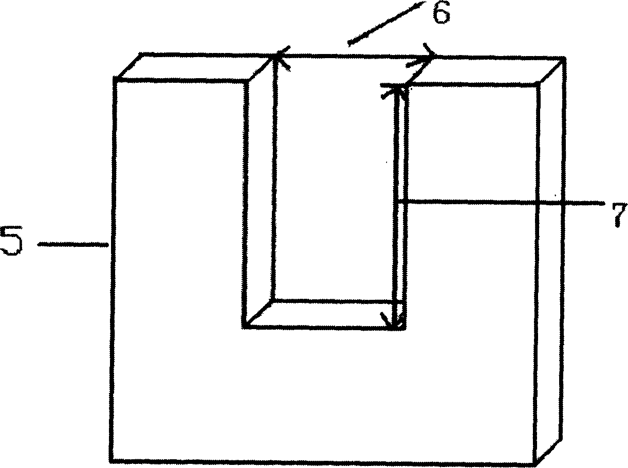
[0024] A laser bar with a length of 12mm and a width (laser cavity length) of 750um is coated. then in Figure 4 The concave plate in the outer layer can have a concave width of about 10.5mm; the concave plate in the middle can have a concave width of about 12.5mm, and the thickness of the concave plate can be 760um. The concave depth can be 5mm shallower than that of the concave plates on both sides, and the thickness of the strip thin plate can be 750um.

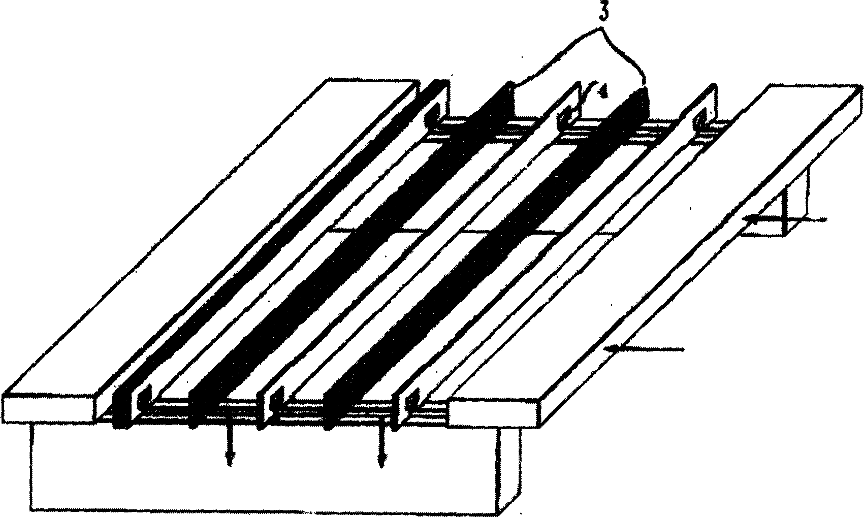
[0025] For the fixture strip device for semiconductor laser cavity surface coating, the base 17 is a flat plate with a strip plate 18 fixed on the base, and a strip plate 19 is connected with the strip plate 18 fixed on the base. Three concave plates 9 stacked together are sandwiched between these two shaped plates.

[0026] When in use, the three concave plates are assembled together by screws, such as Figure 4 Shown in the three concave plates 9 stacked together in the middle, and fixed on the mounting device base 17...


PUM


Abstract

This invention provides a clamp used semiconductor laser cavity face coating composed of three parallel concave plates, a rectangular thin plate and a block for fixing and gripping. This invented strip installing device includes a vertical slide unit, a horizontal slide unit and a base, the vertical and slide units are same in structure all constituting a slide guide and a screw stem for adjusting the slide and a slide block.

Description

technical field [0001] The present invention relates to a kind of fixture device that is used for semiconductor laser cavity surface film coating, more specifically, the present invention relates to a kind of fixture that is used for fixing semiconductor laser chip bar and is convenient to carry out cavity surface film coating and is convenient for laser chip bar to be loaded into The strip loading device for a fixture belongs to the technical field of semiconductor laser technology. Background technique [0002] Since the advent of semiconductor lasers in the early 1960s, it has attracted more and more attention because of its many advantages. However, the natural cleavage surface of the semiconductor laser has a reflectance of about 30%, which is not an ideal value, and the natural cleavage surface is easily oxidized or polluted in the air, which reduces the performance of the laser. In order to solve these problems, semiconductor lasers are usually coated on the cavity s...

Claims


Application Information

Patent Timeline
Patent Type & Authority Applications(China)
IPC IPC(8): B25B1/20B25B5/02H01S5/10
Inventor 沈光地徐晨舒雄文邹德恕陈建新高国
Owner BEIJING UNIV OF TECH
Why Eureka
Try Eureka