Method for detecting voltage zero cross near fault in travelling wave protection

A technology of voltage zero-crossing and traveling wave protection, which is applied in the direction of emergency protection circuit devices, fault locations, and measuring electricity. convenient effect

A technology of voltage zero-crossing and traveling wave protection, which is applied in the direction of emergency protection circuit devices, fault locations, and measuring electricity. convenient effect

CN1610206AInactive Publication Date: 2005-04-27KUNMING UNIV OF SCI & TECH

Image

  • Method for detecting voltage zero cross near fault in travelling wave protection
  • Method for detecting voltage zero cross near fault in travelling wave protection
  • Method for detecting voltage zero cross near fault in travelling wave protection

Examples


Embodiment Construction

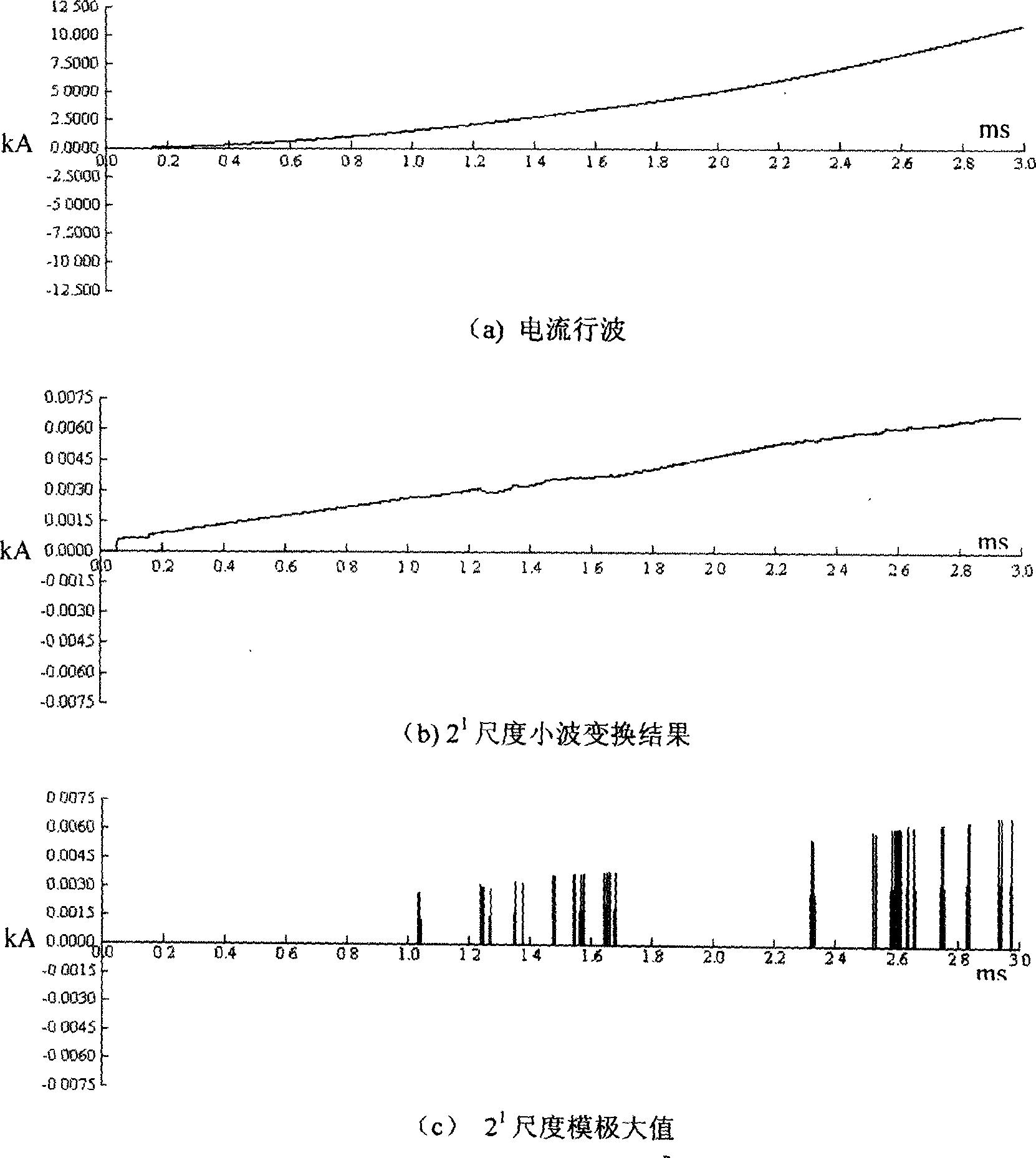
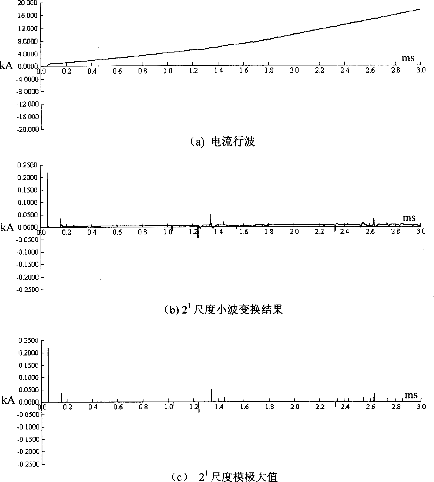
[0026] The research shows that most of the wavelet transform waveforms of the current traveling wave are far away from the time axis when the fault is near the voltage zero crossing, and most of the wavelet transform waveforms of the current traveling wave are close to the time axis when the fault is not near the voltage zero crossing. Therefore, the identification of faults near the voltage zero crossing should be judged as a whole, not just based on some points in the waveform. The concrete implementation steps of this method are as follows:

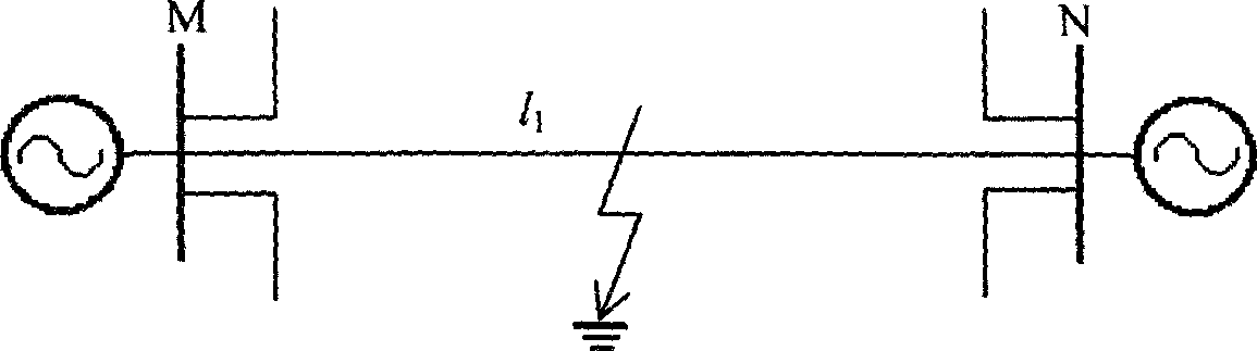
[0027] (1) When the traveling wave protection detects a traveling wave of a certain intensity, it starts and records the three-phase current traveling waves;

[0028] (2) Use the phase-mode transformation matrix T formula to calculate three linear-mode traveling waves and their energy, and select a linear-mode traveling wave with the largest energy for the following calculation; the phase-mode transformation matrix is T ...


PUM


Abstract

The present invention belongs to the field of relay protection technology for electric power system. Based on the characteristic that the small scale wavelet conversion waveform of current traveling wave has its main part far from the time axis while voltage zero-cross failure and near to the time axis normally, phase-analog conversion matrix T is used in calculating three line mode traveling waves and their energy, one line mode traveling wave with maximum energy is selected for wavelet conversion, and the number of the points with values exceeding the maximum Kw is calculated to judge whither to have zero-cross failure. The present invention provides reliable and effective method capable of separating zero-cross failure from other failures.

Description

Technical field: [0001] The invention relates to a detection method for faults near voltage zero crossing in traveling wave protection, which belongs to the technical field of electric power system relay protection. Background technique: [0002] Most of the existing protection devices are based on the protection principle of power frequency quantity. It regards the traveling wave (transient state) process after the fault as interference, tries to filter it out, and only uses the steady state quantity after the fault (reference 1 , 2), and the steady-state quantity after the fault is almost not affected by the fault closing angle, so the power frequency quantity protection is almost not affected by the fault closing angle. Different from the power frequency protection, the traveling wave protection is formed according to the propagation, refraction and reflection of the traveling wave caused by the fault on the line. It uses the high frequency signal caused by the fault and ...

Claims


Application Information

Patent Timeline
27 Apr 2005
Publication
CN1610206A
IPC
G01R31/00; G01R31/08; H02H7/26
Inventors
束洪春; 司大军