Forced circulation evaporation cooling device of hydraulic generator stator

A hydro-generator and generator stator technology, applied in cooling/ventilation devices, electromechanical devices, electric components, etc., can solve the problems of increasing the manufacturing cost of the unit and reducing the reliability, saving investment and operating costs, and reducing replacement. The effect of improving safety and reliability

Inactive Publication Date: 2005-05-18
INST OF ELECTRICAL ENG CHINESE ACAD OF SCI
View PDF1 Cites 6 Cited by
  • Summary
  • Abstract
  • Description
  • Claims
  • Application Information

AI Technical Summary

Problems solved by technology

So many joints make the manufacturing, installation, and maintenance of the unit a lot of work, which increases the manufacturing cost of the unit
Also reduces the reliability of unit operation

Method used


Image

  • Forced circulation evaporation cooling device of hydraulic generator stator
  • Forced circulation evaporation cooling device of hydraulic generator stator
  • Forced circulation evaporation cooling device of hydraulic generator stator

Examples


Embodiment Construction

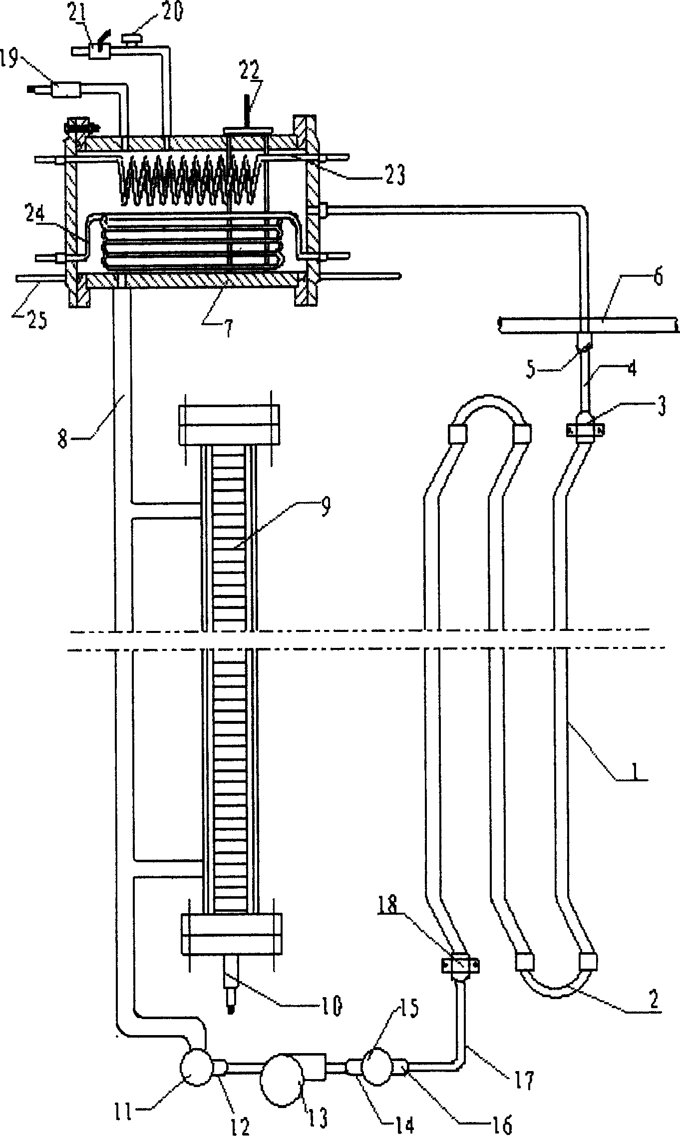
[0043] figure 1Shown is a forced circulation evaporative cooling device for the stator winding of a vertical hydroelectric generator. For the sake of brevity, a wire bar group in which three stator wire bars are connected in series is taken as an example for schematic illustration. The three stator bars are connected end-to-end through the parallel head cover 2 to form a serial stator bar group 1 . The upper end of the stator bar group 1 is connected with the upper insulating lead pipe 4 through the electro-hydraulic separation joint 3 . The electro-hydraulic separation joint is a fixed part that seals the insulating lead pipe and the stator bar. The upper insulating lead pipe 4 is connected with the gas collecting pipe 6 through the sealing joint 5 . The air collecting pipe 6 is connected with the cooling space of the condenser 7 again. The cooling space of the condenser 7 is connected with the liquid return pipe 8 . The liquid return pipe 8 is connected with the magneti...


PUM


Abstract

This invention relates to a cooling technology of motors providing a forcing circulation evaporation cooling device of a hydrogenrerator stator winding connection pipes connect the stator winding, a condenser, a pressure circulation pump and electro-hydraulic separation joints to an evcaporation cooling loop filled with evaporation cooling medium and a pressure circulation pump forcing the circulation of the evaporation cooling medium is also in the loop, every line-rod set consisting hollow heads and solid leads in the stator winding contains odd N serial line-rods, two leading out ends of the line rod set are connected with the up and down insulation lead pipes by the electro-hydaulic separation joints, several line-rod sets and a condenser constitute an independent evaporation cooling loop.

Description

Technical field: [0001] The invention belongs to the cooling technology of a hydroelectric generator, and provides a forced circulation evaporative cooling device for a stator winding of a hydroelectric generator. Background technique: [0002] There are two main traditional cooling methods for hydro-generators: air cooling and water cooling. The air cooling unit is an external cooling mode. It cools by blowing air outside the winding, mainly relying on the specific heat of the air to absorb heat, so the cooling effect is poor. At the same time, due to the limitation of the ultimate capacity, this cooling method limits the development of the hydroelectric generator to a larger capacity. The water internal cooling unit is to pressurize the water pump to make the water flow in the hollow wire of the winding to take away the heat. Because the specific heat of the water is large and the viscosity is small, its cooling effect is good. However, due to the high pressure of the wa...

Claims


Application Information

Patent Timeline
Patent Type & Authority Applications(China)
IPC IPC(8): H02K9/19
Inventor 阮琳顾国彪钱光岳田新东傅德平袁佳毅
Owner INST OF ELECTRICAL ENG CHINESE ACAD OF SCI
Why Eureka
Try Eureka