Plate spring skeleton hydrulic pneumatic flexible bending joint

A bending joint, hydro-pneumatic technology, applied in manipulators, manufacturing tools, joints, etc., can solve the problems of high manufacturing cost, complex structure, insensitive response, etc., and achieve high dynamic control accuracy, small fluid flow, and good coordination. Effect

Inactive Publication Date: 2005-05-25
JIANGNAN UNIV
View PDF1 Cites 49 Cited by
  • Summary
  • Abstract
  • Description
  • Claims
  • Application Information

AI Technical Summary

Problems solved by technology

[0002] Before the present invention was made, in the prior art, for bending joints: generally, various types of motors or hydraulic pressure were used as power, and combinations of various mechanical structures, hydraulic cylinders, motors, etc. were used as actuators; the above methods were Rigid structure, high precision control requirements, complex structure, large volume, high manufacturing cost
There is also a rubber wall driven by air pressure (a circular rubber tube that is deformable and stores energy, and a helical wire that restricts radial expansion is clamped inside the

Method used


Image

  • Plate spring skeleton hydrulic pneumatic flexible bending joint
  • Plate spring skeleton hydrulic pneumatic flexible bending joint
  • Plate spring skeleton hydrulic pneumatic flexible bending joint

Examples


Embodiment Construction

[0020] Below the present invention will be further described in conjunction with the implementation of scheme I in the accompanying drawings:

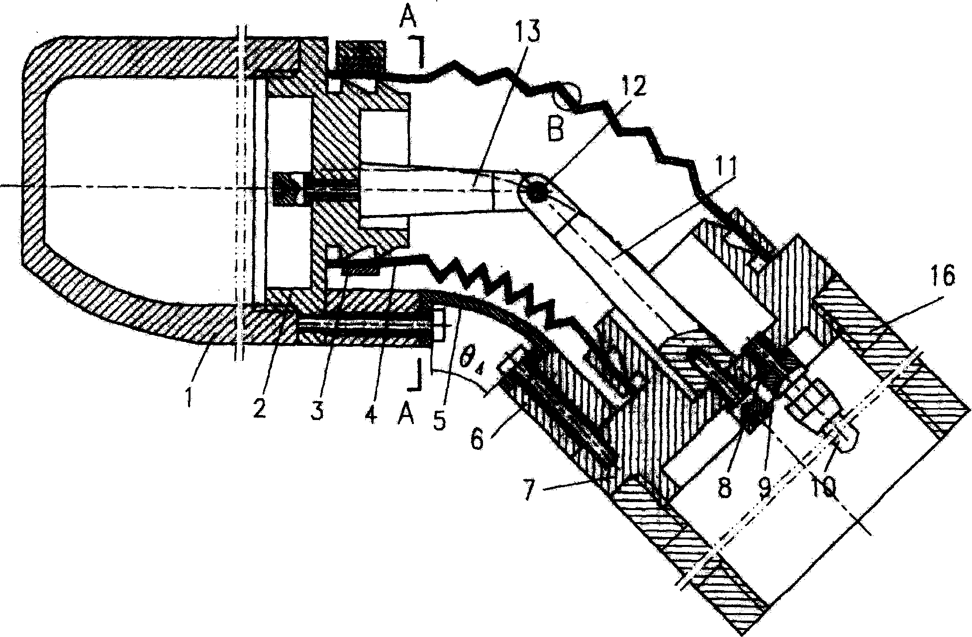
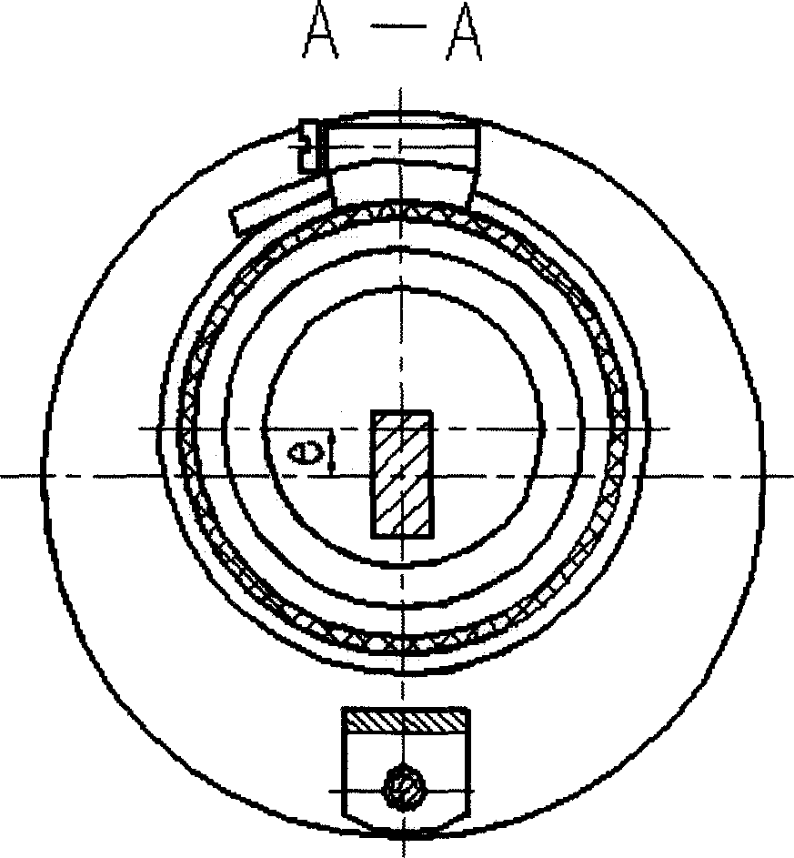
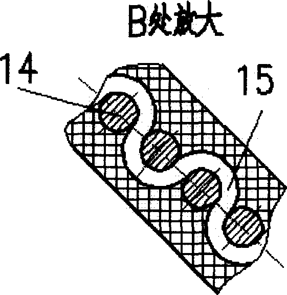
[0021] The joints of plan I are mainly composed of head section 1, head seat 2, clamp 3, wave shell elastic body 4, plate spring 5, cushion block 6, tail stock 7, gasket 8, pipe joint 9, hose 10, long hinge seat 11. Hinge 12, short hinge seat 13, circular weft 14, winding warp 15, middle section 16, etc.

[0022] The wave shell elastic body 4 is clamped on the bayonet of the headstock 2 and the tailstock 7 by the clamp 3, and the two ends of the leaf spring 5 are fixed on the headstock 2 and the tailstock 7 through the pads 6; inside the joint, two The inner hex bolts pass through the gasket 8 respectively to fix the long hinge seat 11 and the short hinge seat 13 on the tailstock 7 and the headstock 2, and the long hinge seat 11 and the short hinge seat 13 are connected by a hinge 12; The headstock 2 is threaded, the middle section 16...


PUM


Abstract

A pneumatic flexible joint for robot or manipulator features that the leaf spring is used as its flexible skeleton and the corrugated shell is pneumatically expanded for providing the muscle power. Under the action of leaf spring, it can be bent but not axially extended. Its advantages are high flexibility and control accuracy, and low energy consumption.

Description

Technical field: [0001] The invention relates to a flexible bending joint of a plate spring skeleton liquid pneumatic type, which can be used as various joints such as elbows and legs of robots, and is especially suitable for mechanical fingers composed of multiple bending joints, and multiple mechanical fingers can be used The combined operation manipulator is used as an executive mechanism of automation equipment, and belongs to the technical field of robot and manipulator application. Background technique: [0002] Before the present invention was made, in the prior art, for bending joints: generally, various types of motors or hydraulic pressure were used as power, and combinations of various mechanical structures, hydraulic cylinders, motors, etc. were used as actuators; the above methods were The rigid structure requires high control precision, and the structure is complicated, the volume is large, and the manufacturing cost is high. There is also a rubber wall driven...

Claims


Application Information

Patent Timeline
IPC IPC(8): B25J17/00
Inventor 章军须文波吕兵
Owner JIANGNAN UNIV
Why Eureka
Try Eureka