Ice making mechanism for ice maker

A technology of ice maker and ice water, which is applied in ice making, ice making, lighting and heating equipment, etc. It can solve the problems of poor ice making efficiency, melting of ice mass, dark appearance of ice mass, etc.

Inactive Publication Date: 2005-06-01
HOSHIZAKI ELECTRIC CO LTD
View PDF0 Cites 18 Cited by
  • Summary
  • Abstract
  • Description
  • Claims
  • Application Information

AI Technical Summary

Problems solved by technology

[0009] In the closed cell type ice making mechanism 10 or the open cell type ice making mechanism 11 respectively, if the concentration of impurities contained in the ice making water stored in the ice making water tank 20 increases too much, it will cause the following problems: the ice The darkening of the clumps spoils its appearance, or the clumps melt prematurely, or the clumps stick to each other very easily in the ice storage compartment
[0010] In this case, the ice making water that was cooled in the previous ice making operation was not fully utilized, resulting in a large energy loss
In addition, since the ice-making water stored in the ice-making water tank 20 reaches normal temperature, there arises a problem that it takes time to cool a large amount of ice-making water stored in the ice-making water tank 20 for the next ice-making operation, so The longer ice making cycle results in poor ice making efficiency

Method used


Image

  • Ice making mechanism for ice maker
  • Ice making mechanism for ice maker
  • Ice making mechanism for ice maker

Examples


Embodiment 1

[0027] (summary)

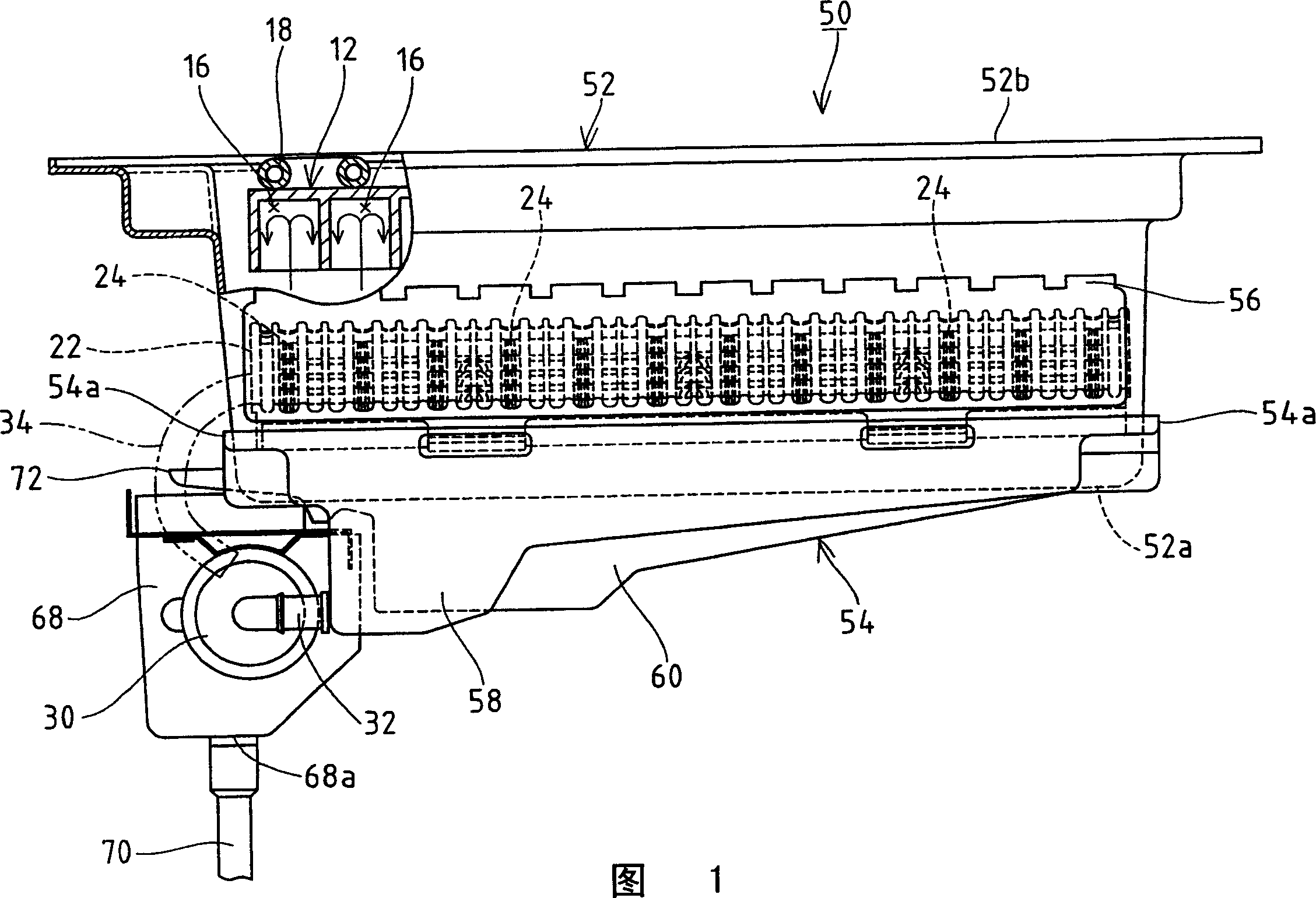
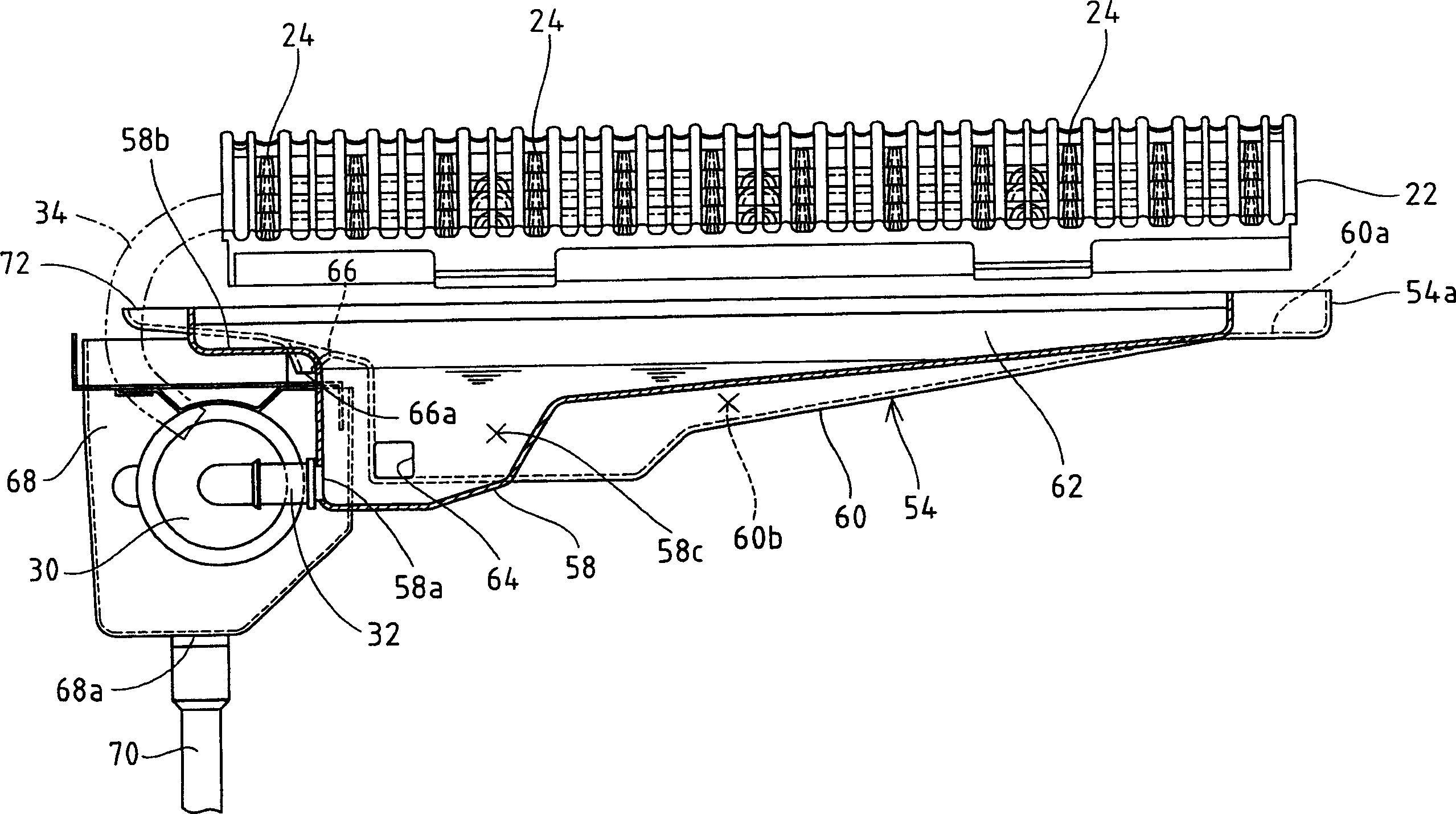
[0028] As shown in Figure 1, the ice-making mechanism 50 of embodiment 1 comprises: an ice-making chamber (ice-making part) 12, and this ice-making chamber 12 is made up of a large amount of ice-making chambers 16, and this ice-making chamber 16 is installed in box-shaped Near the top of the machine base 52 so as to open downwards; a water tray 22 with a plurality of water injection holes 24, the plurality of injection holes are associated with each ice making chamber 16 respectively; An ice-making water tank 54, which is used under storage conditions to store the required amount of ice-making water and to collect unfrozen water as described below. At the top of the ice-making chamber 12, the evaporating pipes 18 communicated with the refrigeration system (not shown) are arranged in close contact with each other and in a zigzag form to circulate the refrigerant during the ice-making operation and thus force the above-mentioned ice-making chamber 16 cool down....

Embodiment 2

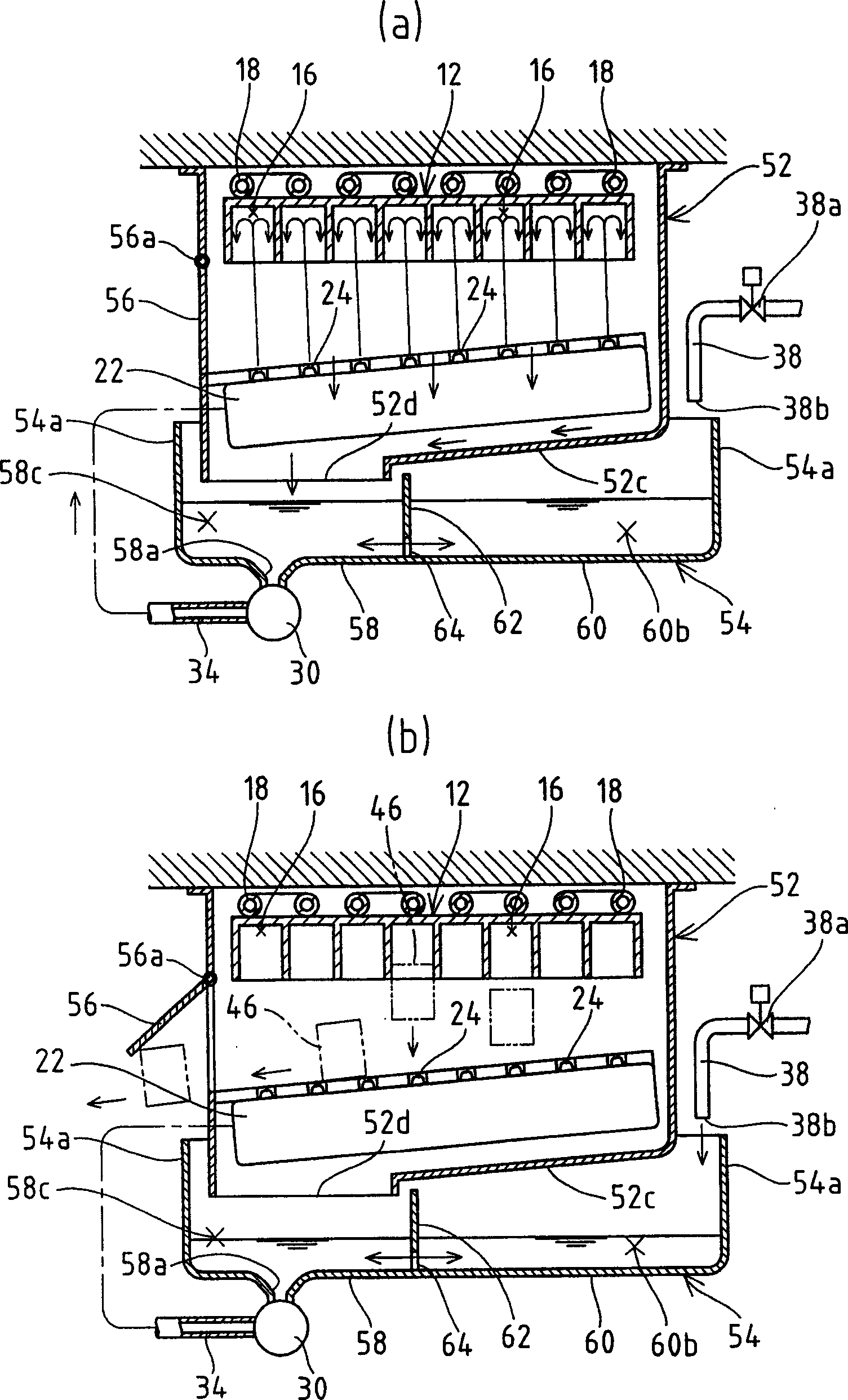
[0048] In Embodiment 1, the open unit type ice-making mechanism 50 is applied, and its ice-making water tank 54 is internally divided into a circulation tank part 58 and a storage tank part 60, and it has a guide plate (guide device) 52c, which guide plate It is used to guide the unfrozen water in the ice making chamber (ice making part) 12 only to the circulation tank portion 58 . However, for Figure 5-9 In the illustrated second embodiment, a closed unit type ice making mechanism 80 is described, the ice making water tank 82 is internally divided into a circulation tank part 84 and a storage tank part 86, and it has a guide plate (guide means ) 90, the guide plate is used to guide the unfrozen water in the ice making compartment (ice making part) 12 only to the circulation tank portion 84. The basic structure and reference of the ice making mechanism 80 of Embodiment 2 Figure 10 The structure of the closed cell type ice making mechanism 10 described is substantially the s...


PUM


Abstract

An ice-making water tank (54) can improve ice-making efficiency by preventing the concentration of impurities contained in ice-making water from increasing. The ice-making water tank (54) is divided into a circulation tank part (58) and a storage tank part (60) by a partition (62). The ice-making water stored in the circulation tank part (58) and the ice-making water stored in the storage tank part (60) can convect each other through a communication hole (64). The storage tank section (60) has a capacity greater than that of the circulation tank section (58). Above said sump part (60) is covered with a guide plate (52c) of the machine base (52), the unfrozen water cooled during ice making operation is only collected into the circulation tank through an opening (52d) (58). The opening (52d) opens downward above the circulation tank (58).

Description

technical field [0001] The present invention relates to an ice-making mechanism of an ice-making machine, in particular to an ice-making mechanism for an ice-making machine that supplies ice-making water to a plurality of downward-opening ice-making cavities by spraying upwards, so that the mechanism can Ice cubes (ice cubes) are produced continuously. Background technique [0002] The jet-type automatic ice maker supplies ice-making water into a plurality of downward-opening ice-making cavities by spraying upwards, so that ice cubes (ice cubes) can be continuously produced. Such ejector-type ice makers are conveniently used in coffee shops, kitchens of restaurants, and other places. Such as Figure 10 As shown, the ice making mechanism of this jet type automatic ice maker includes a kind of ice making mechanism 10 called a closed unit type (for example, refer to the utility model No. Hei 6-28568 of Japanese unexamined registration publication number ). The ice-making mec...

Claims


Application Information

Patent Timeline
Patent Type & Authority Applications(China)
IPC IPC(8): F25C1/22F25C1/04
CPCF25C1/045F25C2400/14F25C2500/08
Inventor 石富邦彦川隅政明高桥贤二门胁静马长泽伸一细木忠治
Owner HOSHIZAKI ELECTRIC CO LTD
Why Eureka
Try Eureka