
Photo etching alignment mark in use for X-ray

A lithography alignment and X-ray technology, applied in the field of X-ray lithography alignment marks, can solve problems such as difficult guarantee, deformation, high system accuracy, etc., and achieve the effect of improving alignment accuracy

Inactive Publication Date: 2005-06-15
INST OF MICROELECTRONICS CHINESE ACAD OF SCI
View PDF0 Cites 9 Cited by
  • Summary
  • Abstract
  • Description
  • Claims
  • Application Information

AI Technical Summary

Problems solved by technology

For the marks on this mask and silicon wafer, the number of lines used by the data acquisition system is small, so it is difficult to ensure high system accuracy, and when the mask and silicon wafer are subjected to external pressure and other factors When deformed, this kind of mark will also be deformed, and its redundancy for errors is very small, which will cause greater alignment deviation and reduce the alignment accuracy of the system

Method used


Image

  • Photo etching alignment mark in use for X-ray
  • Photo etching alignment mark in use for X-ray
  • Photo etching alignment mark in use for X-ray

Examples


Embodiment Construction

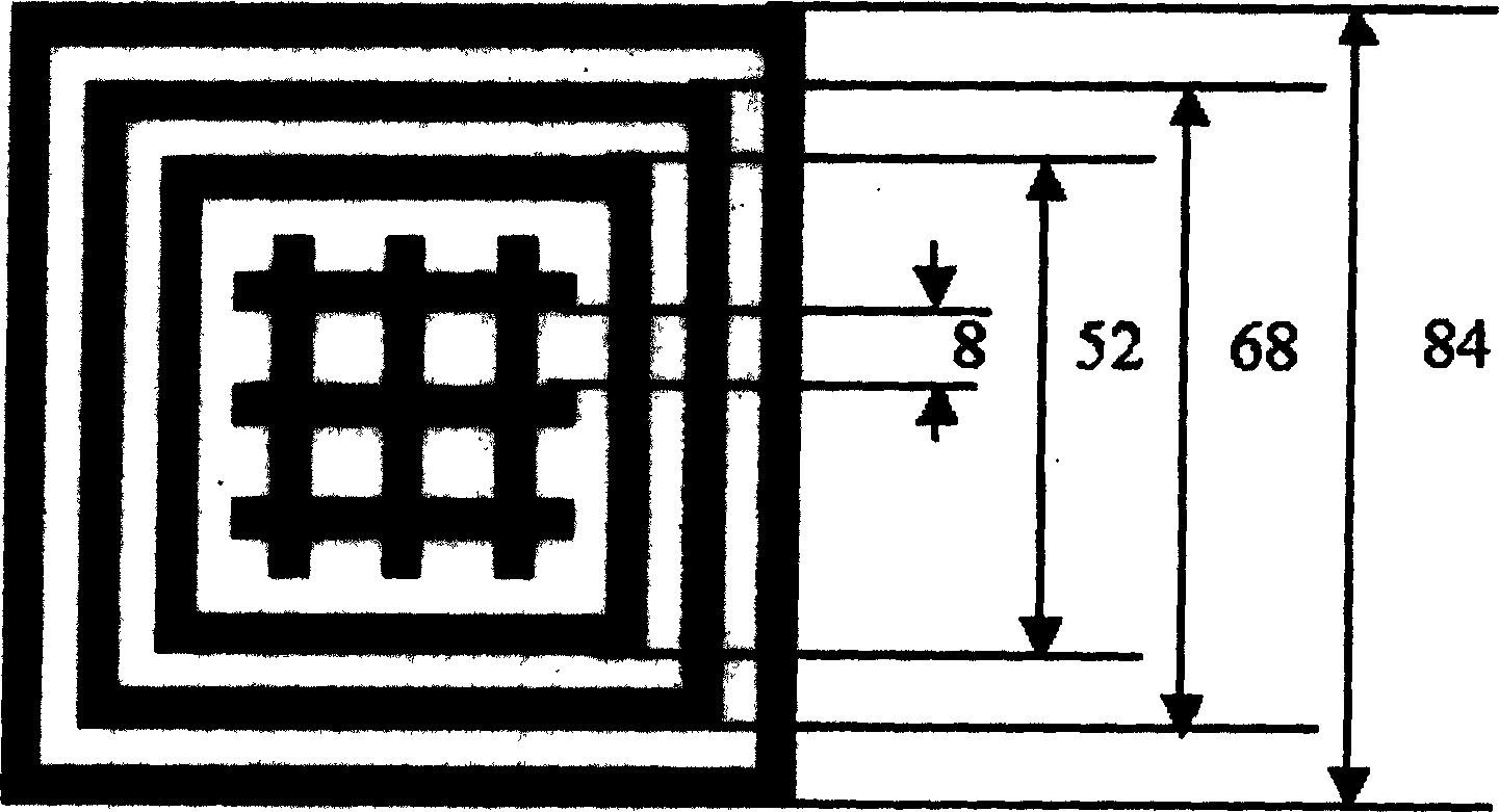
[0014] The alignment mark of the present invention consists of two parts, including three square marks on the mask and six straight line marks on the silicon wafer. The advantages of the new invention will be described below by comparison.

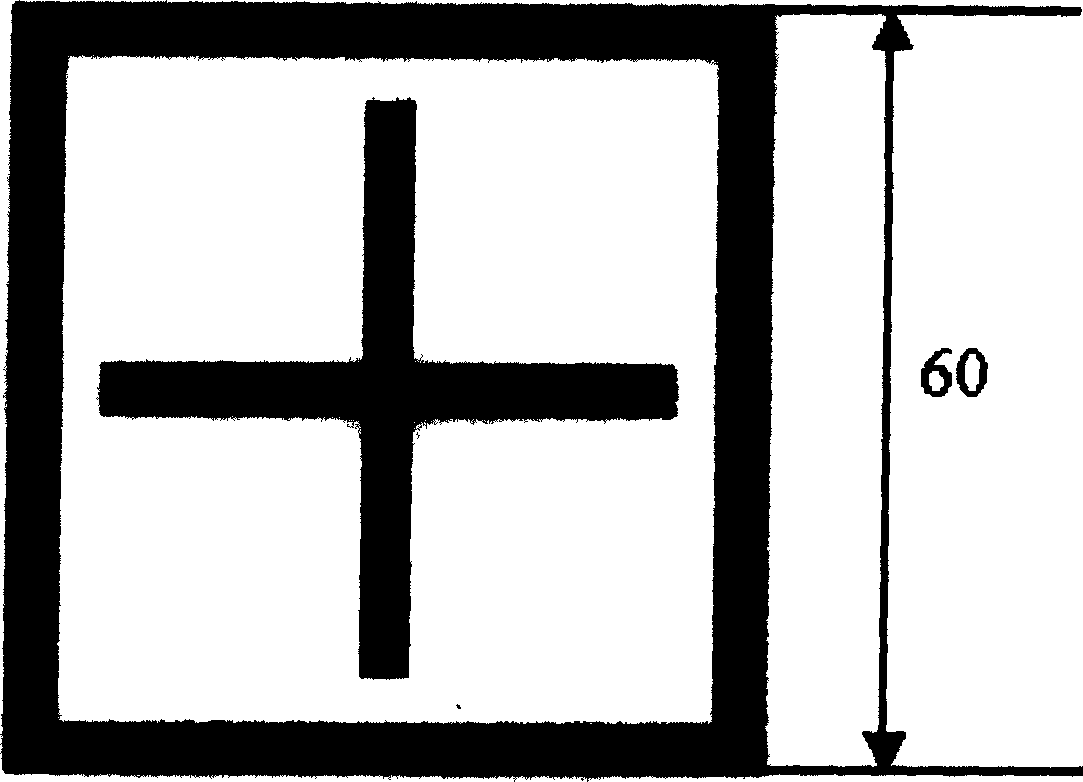
[0015] For the original alignment marks a box and a cross such as figure 1 As shown, it is assumed that the central coordinates of the left and right cross marks on the silicon chip recognized by the computer after image processing are (X W1 , Y W1 ), (X W2 , Y W2 ), the center coordinates of the coordinate box mark on the mask are (X M1 , Y M1 ), (X M2 , Y M2 ), then the values ​​of ΔX (offset in X direction) and ΔY (offset in Y direction) can be expressed by the following formula:

[0016] ΔX = ( X W 1 - X ...


PUM

PropertyMeasurementUnit
widthaaaaaaaaaa

Abstract

This invention relates to labels used in the alignment of x-ray photoetching. The labels are composed of two labels on the mask and silicon chip, which are composed of three square blocks on the mask and six cross-lines on the silicon chip, among which, the three square blocks are sleeved orderly from small to big and share one central point, the label is set on SiNx film. Among the six cross lines, three are arrayed horizontally in equal distance the other three are arrayed vertically in equal distance, the label is set on the silicon chip substrate. This invented alignment label has a redundancy to the deformation of the mask and silicon chip, its uniform value can make alignment system to get more accurate position information of the label, to increase the alignment accuracy of photoetching.

Description

technical field [0001] The invention relates to the technical field of X-ray lithography alignment, in particular to a new mark applied to X-ray lithography alignment. Background technique [0002] Synchrotron radiation X-ray lithography (XRL) is a very good lithography technique that can be used for resolutions of 100nm and below. In order to meet the requirements of device production and process experiments, it is necessary to improve the alignment accuracy of the alignment system. Only with the guarantee of high alignment accuracy and overlay accuracy can it be possible to manufacture reliable devices and circuits. The requirements for the accuracy of the alignment system are constantly increasing, so it is necessary to seek different methods to improve the accuracy through continuous innovation. There are many measures to improve the accuracy. Here we introduce the design and optimization of the alignment marks of the system. Through the new alignment marks to accurate...

Claims


Application Information

Patent Timeline
Patent Type & Authority Applications(China)
IPC IPC(8): G03F7/20H01L21/027
Inventor 王德强谢常青叶甜春
Owner INST OF MICROELECTRONICS CHINESE ACAD OF SCI
Learn More