Highly efficiency microturbulence celluloid ink flotation cell

A flotation cell and micro-turbulence technology, applied in the field of pulp and paper making, can solve the problems such as the limitation of deinking efficiency of deinking flotation cell, and achieve the effect of simple structure

Inactive Publication Date: 2005-06-29
SOUTH CHINA UNIV OF TECH
View PDF0 Cites 2 Cited by
  • Summary
  • Abstract
  • Description
  • Claims
  • Application Information

AI Technical Summary

Problems solved by technology

[0009] These deficiencies make the deinking efficiency of deinking flotation cells with orifice plate diffusers also limited

Method used


Image

  • Highly efficiency microturbulence celluloid ink flotation cell
  • Highly efficiency microturbulence celluloid ink flotation cell
  • Highly efficiency microturbulence celluloid ink flotation cell

Examples


Embodiment Construction

[0030] The present invention will be further described below in conjunction with the accompanying drawings, but the scope of protection claimed by the present invention is not limited to the scope described in the embodiments.

[0031] The improvements of the present invention are as follows:

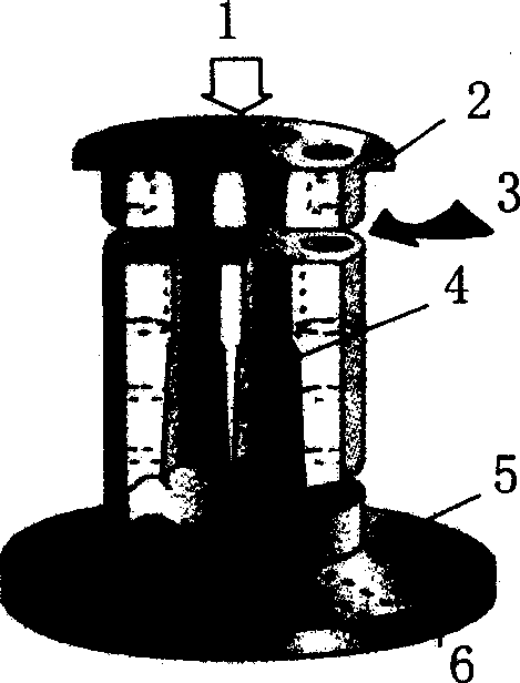
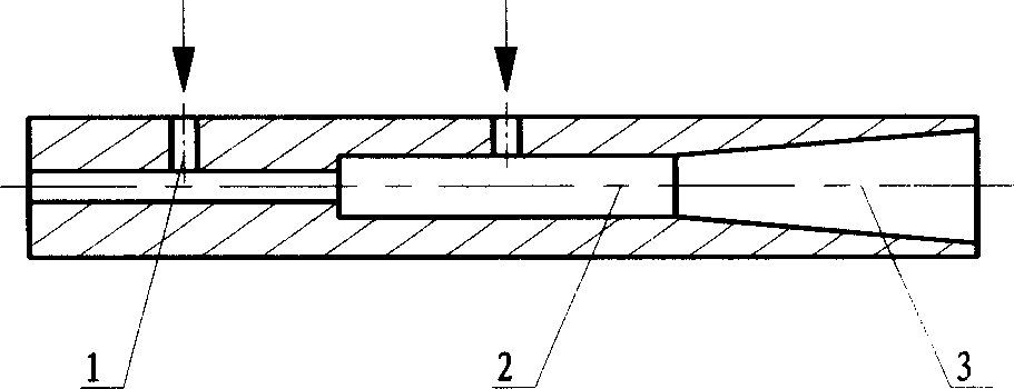
[0032] (1) attached figure 1 It is a schematic structural view of an orifice diffuser in the prior art, consisting of a feed inlet 1, an orifice 2, an air inlet 3, a step diffuser 4, a bottom plate 5 and a discharge outlet 6; the present invention uses The last sudden expansion tube of the stepped diffuser 4 is changed to a gradual expansion tube, as attached image 3 Shown:

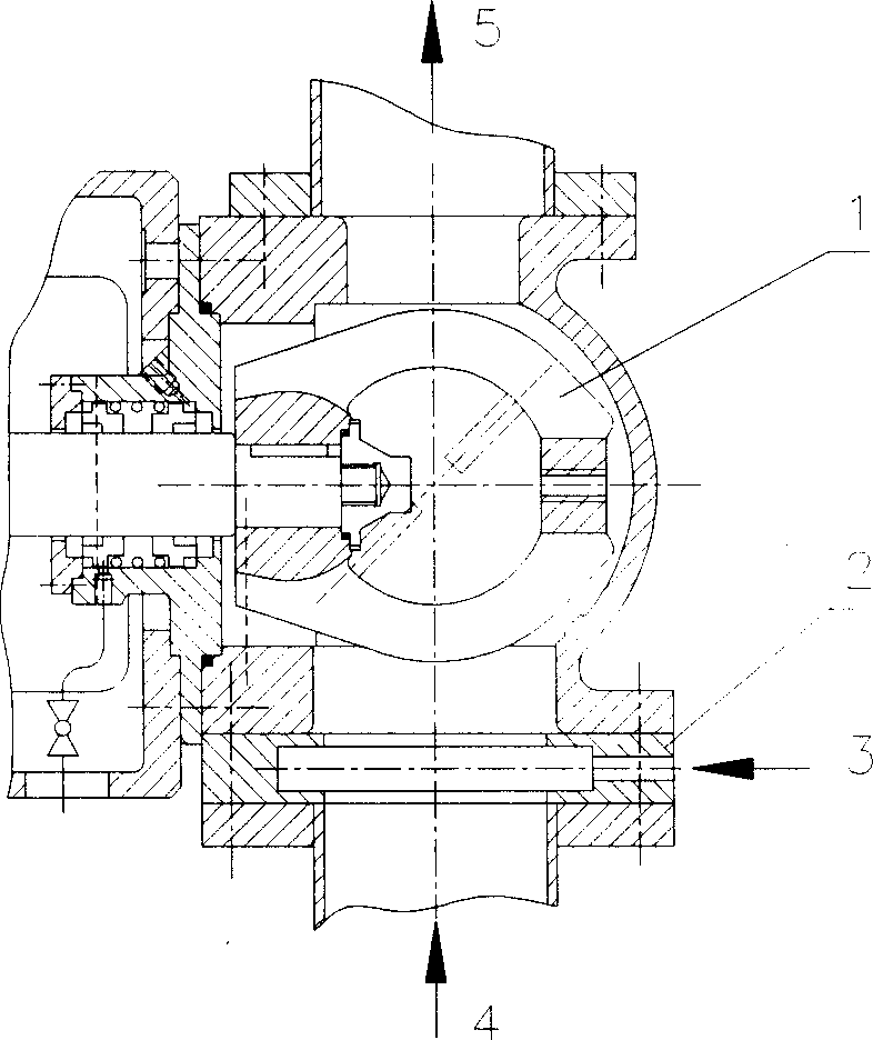
[0033] (2) Add a turbulence generator before the stepped diffuser, as attached figure 2 As shown in the figure, the air bubble forming and uniform mixing device with the slurry is composed of an air-filling element and a turbulent flow generator;

[0034] (3) A deflector is set in the flotation cell to form a...


PUM


Abstract

The invention unfurls a kind of float choosing slot for taking off ink of high effect. Compared with the current technique, the invention makes these changes: (1) add water current occur fix in front of the stairs spreading fix, the mixing equipment is made by air fix and water current occur fix; (2) change the last tube of the stairs spreading fix to the gradual spreading tube; (3) in the float choosing slot, there is float board and formatting the paragraph. By the float board, we can control the liquid stopping time in the float choosing slot, make the ink grains float to the surface, collect them by most in the spirit collection slot.

Description

technical field [0001] The invention relates to the technical field of pulping and papermaking, in particular to a micro-turbulence high-efficiency deinking flotation cell. Background technique [0002] At present, the more advanced waste paper deinking production in our country is usually a process of flotation or a combination of flotation and washing. Firstly, it is pulped, the paper is dispersed into a fiber suspension (pulp), and the fibers and the printing ink on it are fully separated under the action of deinking chemicals, and then the ink particles are separated from the pulp in the flotation tank remove. [0003] The flotation cell is the core professional equipment in the waste paper deinking process. Since most printing inks are oil-based substances, the ink particles have obvious hydrophobicity. Through the effect of surface tension, the ink particles of different sizes (with a particle size of 10-100 μm) can be trapped by the air bubbles and floated to the su...

Claims


Application Information

Patent Timeline
Patent Type & Authority Applications(China)
IPC IPC(8): B03D1/14
Inventor 陈克复李军杨仁党莫力焕官日彬陈其峰
Owner SOUTH CHINA UNIV OF TECH
Why Eureka
Try Eureka