
A WDM optical transmission system with automatic link gain adjustment and method thereof

A link gain and automatic adjustment technology, applied in the direction of wavelength division multiplexing system, etc., can solve the problems of automatic optical power reduction, difficult time, miscontrol, etc., and achieve the effect of simple and easy measurement

Inactive Publication Date: 2005-06-29
FENGHUO COMM SCI & TECH CO LTD
View PDF0 Cites 19 Cited by
  • Summary
  • Abstract
  • Description
  • Claims
  • Application Information

AI Technical Summary

Problems solved by technology

[0005] However, the previously proposed automatic gain adjustment method uses the measurement of the power of the main optical channel to calculate the link attenuation of the span section
However, since the power change of the main optical channel is affected by the following factors, the number of light source channels changes, the parameters of all relay station equipment in the N spans before the amplifier of this station change, the aging of optical cables, and the process of automatic optical power reduction (APR) , power supply of this site and other factors
These multiple factors mixed together will cause changes in the main optical power received by the station, so the method of calculating the link attenuation of the span section by detecting the difference between the receiving and receiving optical power of the main optical channel is susceptible to interference
In addition, when comparing the transmit power of the front station with the receive power of the back station, due to the delay caused by power detection, line coding and decoding, transmission delay and other processes, it is not easy to achieve "synchronization" of the sampling of the transmitted and received optical power values. That is to say, the transmitted / received optical power for comparison is probably not collected at the "same moment"
Due to the influence of the above factors, on the one hand, the adjustment of EVOA may be very frequent, resulting in the mutual interference of optical amplification relay stations on the relay stations at all levels in the whole system, and also increasing the burden of the transmission power value of the optical monitoring channel and the calculation of the value by the processing equipment in the relay station. processing burden
On the other hand, it is not easy to detect the transmit / receive optical power at the "same moment" in terms of time, which has the potential danger of misadjusting and miscontrolling EVOA

Method used


Image

  • A WDM optical transmission system with automatic link gain adjustment and method thereof
  • A WDM optical transmission system with automatic link gain adjustment and method thereof
  • A WDM optical transmission system with automatic link gain adjustment and method thereof

Examples


Embodiment approach

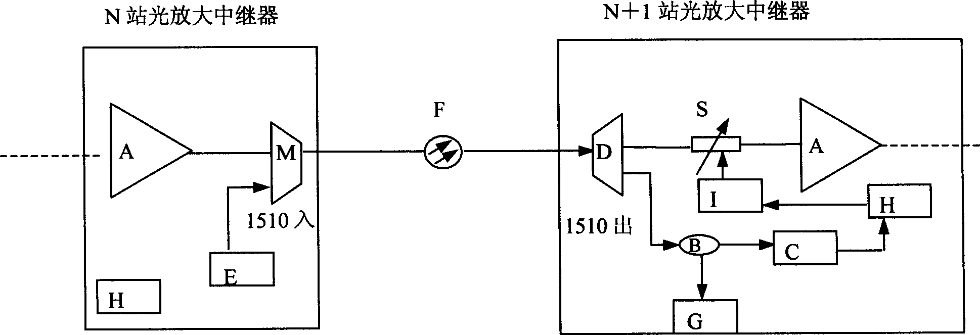
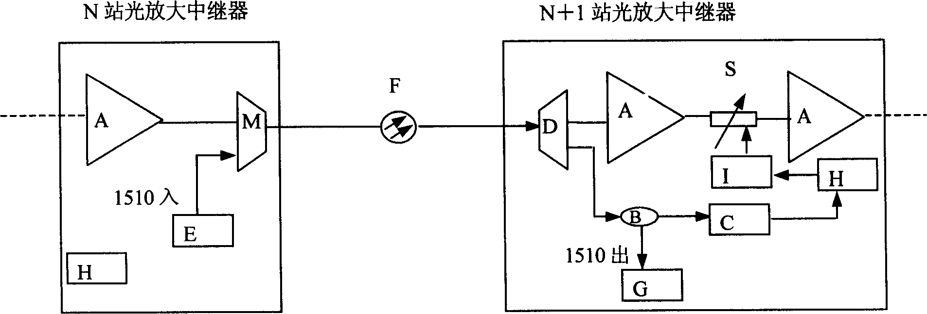
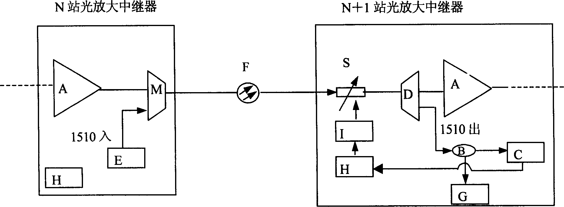
[0056] The present invention will be further described below in conjunction with drawings and embodiments. In the specific implementation process of the present invention, the OSC transmitting part of the upstream station (N station) has one implementation mode, while the OSC receiving processing part of the downstream station (N+1 station) has three implementation modes. figure 1 , figure 2 and image 3 Shown are three specific implementations of the system of the present invention. For ease of illustration, the actual dual-fiber bidirectional transmission system only shows one transmission direction in the figure. At the same time, for the upstream station, that is, the functional block diagram of the optical amplification relay station of the Nth station in the figure, only the sending part is marked, and other important components in the optical transmission link, such as Raman optical amplifier, dynamic gain equalization ( Components such as the DGE) and the dispersion...


PUM

PropertyMeasurementUnit
Wavelengthaaaaaaaaaa

Abstract

This invention relates to WDM light transmission system of a link gain automatic adjustment and an automatic adjust method. The invention detects a received light power of a light monitor channel wavelength at the lower-reach station of a given cross distance section and computes the fiber circuit loss of said section by the difference between sent light power of the upper reach station and the received light power of the lower reach station, then to adjust the light power attenuation value of the light adjustable attenuator of said section lower reach station based on the loss to match the circuit loss and the gain of light amplified relay.

Description

technical field [0001] The present invention relates to a wavelength division multiplexing optical transmission system with automatic link gain adjustment and a link gain automatic adjustment method used in the system, and the present invention is especially used for optical transmission in an optical dense wavelength division multiplexing (DWDM) transmission system Link single-span section gain automatic adjustment and full link gain automatic adjustment technology enable the optical amplification relay section and the entire optical transmission link in the DWDM system to automatically and effectively perform real-time automatic adjustment of link gain. Background technique [0002] In the existing WDM transmission system design, the gain of Erbium-doped fiber amplifier (EDFA) is mainly determined by the pump power, pump wavelength, and the length of Erbium-doped fiber. Once the length of Erbium-doped fiber, pumping wavelength, and power are determined Finally, it is not e...

Claims


Application Information

Patent Timeline
IPC IPC(8): H04J14/02
Inventor 叶荣富
Owner FENGHUO COMM SCI & TECH CO LTD
Learn More