RF and baseband subsystems interface

A technology for baseband subsystems and subsystems, which is applied to baseband system components, transmission systems, digital transmission systems, etc., and can solve the problems that the interface does not try to improve bandwidth efficiency, does not solve the waiting time of control commands, and increases costs.

Inactive Publication Date: 2005-07-13
KONINKLIJKE PHILIPS ELECTRONICS NV
View PDF1 Cites 16 Cited by
  • Summary
  • Abstract
  • Description
  • Claims
  • Application Information

AI Technical Summary

Problems solved by technology

[0004] The interface disclosed in document WO 00 / 42744 requires an extra pin, which is only used for the sleep signal, and this extra pin complicates the interface and increases costs
Furthermore, the proposed interface makes no attempt to improve bandwidth efficiency and does not address issues related to latency of control commands

Method used


Image

  • RF and baseband subsystems interface
  • RF and baseband subsystems interface
  • RF and baseband subsystems interface

Examples


Embodiment Construction

[0025] The present invention relates to a digital interface for communicating information and control signals between a baseband subsystem and a radio frequency subsystem in a wireless communication system. Such a wireless communication system may be established according to one of various wireless local area network (LAN) communication standards, such as the HiperLAN2 IEEE 802.11a / b / e / g or the Bluetooth standard. It is to be noted that the present invention encompasses any interface that has features of the present invention and that may otherwise implement current or future wireless standards.

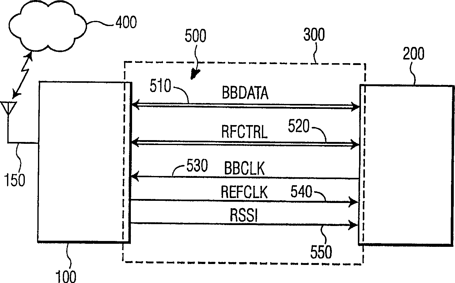
[0026] figure 1 A wireless communication system 300 is shown, and the wireless communication system 300 includes a radio frequency subsystem 100 and a baseband subsystem 200 communicating with each other via a digital interface 500 of the present invention. The radio frequency subsystem 100 receives and transmits radio frequency signals on the wireless network 400 via the antenna 15...


PUM


Abstract

A digital interface for a wireless communication system having a reduced number of connectors. The first connector transmits data signals between the radio frequency subsystem and the baseband subsystem. Data signals represent digital baseband signals received or transmitted over a wireless network. The data signal is a multi-level data signal, and the number of bits of a sample of the digital baseband signal transmitted at one time is greater than 1. The radio frequency circuit synchronizes the transmission of the data signal with the synchronous clock signal provided by the baseband circuit. The baseband circuit controls the operation mode of the wireless communication system through control signals, which represent commands to the radio frequency circuit. The control signals represent commands of various lengths, so important commands can be transmitted quickly.

Description

technical field [0001] The present invention relates to a digital interface between a radio frequency subsystem and a baseband subsystem, and more particularly to a wireless communication system in which the radio frequency circuit and the baseband circuit are established at a remote distance from each other. Background technique [0002] The wireless industry has made proposals for various interface designs, however, these designs are often uniquely related to only one vending machine and / or one platform. Therefore, problems arise when RF subsystems and baseband (BB) subsystems from different manufacturers cannot communicate with each other and operate together. Several parties have attempted to implement their own standard radio interface specifications, but none have been agreed to, and none have the full support of the wireless industry. [0003] An interface-independent proposed vending machine and platform is disclosed in PCT publication WO 00 / 42744, which publication...

Claims


Application Information

Patent Timeline
Patent Type & Authority Applications(China)
IPC IPC(8): G06F3/00H04B1/40H04L12/56H04L25/02
CPCH04W24/00H04W56/00H04W88/085H04B1/40H04W92/04
Inventor O·J·希斯奇G·弗雷德里克斯S·哈赫恩E·里奥
Owner KONINKLIJKE PHILIPS ELECTRONICS NV
Why Eureka
Try Eureka