

Hydrocarbon material catalytic cracking lift pipe reactor
A catalytic cracking and reactor technology, applied in chemical instruments and methods, naphtha catalytic reforming, chemical/physical processes, etc., can solve the problems of poor versatility of equipment and complex engineering, and achieve simple structure, high catalyst density, Reduces the effect of catalyst backmixing
Inactive Publication Date: 2005-07-20
石宝珍
View PDF2 Cites 0 Cited by
- Summary
- Abstract
- Description
- Claims
- Application Information
AI Technical Summary
Problems solved by technology
However, the three-pipe structure is still a conventional design, which is too complicated in engineering and poor in versatility of equipment
Method used
View moreImage
Smart ImageViewing Examples

Examples
Embodiment 2
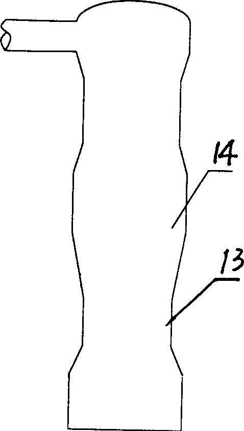
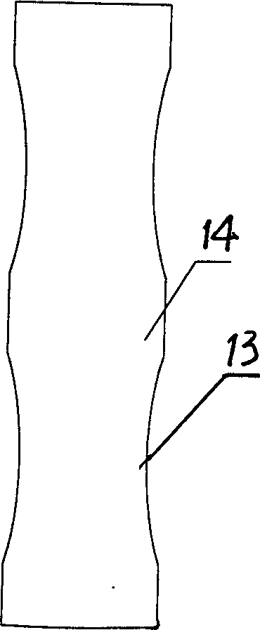
[0014] Embodiment 2. In this embodiment, the height of the first and second reactors 1 and 2 is 5 meters, and the height of the cracking section b is 15 meters. The third reactor 3 has an inverted conical structure with a cone angle of 20 degrees, and its height is 4 meters. The fourth reactor 4 is a zoom-shaped structure, and the longitudinal section structure of the diameter-reducing zone 13 is as follows: image 3 As shown, the diameter of the reduced-diameter zone 13 is 0.7-1 times of the diameter of the non-diameter-reduced zone 14, and the height is 10 meters. Others are the same as embodiment 1.
Login to View More PUM
| Property | Measurement | Unit |
|---|---|---|
| height | aaaaa | aaaaa |
| height | aaaaa | aaaaa |
Abstract
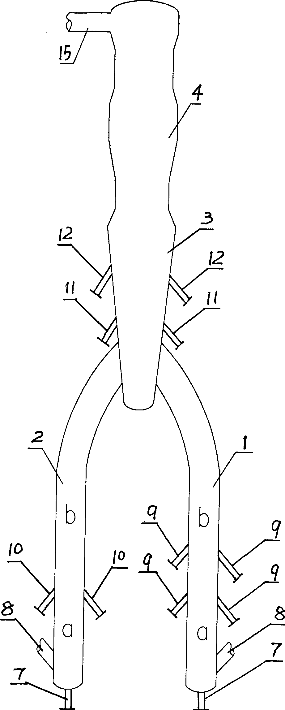
The present invention relates to a catalytic cracking lift pipe reactor for hydrocarbon raw material. It comprises parallelly-arranged first reactor and second reactor and coaxially series-connected third reactor and fourth reactor, the upper ends of first and second reactors are serial-connected with lower end of third reactor, and is formed from prelift stage of lower portion and cracking reaction stage of upper portion, the bottom portion of its prelift stage is equipped with prelift gas inlet pipe, its lower portion is equipped with a catalyst inlet pipe, and the lower portion of its craking stage respectively is equipped with raw material oil inlet pipe nozzle, recycle oil and slurry oil inlet pipe nozzle. Said invention also provides the concrete structure of third and fourth reactors. Said invention can raise gasoline yield by 1%, and the olefin content in the produced gasoline can be reduced by 10-15%.
Description
technical field [0001] The invention belongs to the technical field of petroleum refining equipment, in particular to a hydrocarbon raw material catalytic cracking riser reactor. Background technique [0002] The catalytic cracking unit is one of the important equipment for the secondary processing of raw oil in the refinery, and the riser reactor is the core equipment of the catalytic cracking unit. The existing riser reactor usually adopts a reactor with equal diameter, and the reaction efficiency in the upper part of the reactor is very low. In recent years, many improvements have been made in the riser reactor. For example, Chinese patent applications 99213769.1 and 00134054.9 have proposed a double riser reactor scheme. The double riser reactor is arranged in two sections, the first section (the first lift tube reactor) is used for raw oil cracking. After the reaction product is separated from gas and solid, gasoline enters the second riser reactor in the upper part, a...
Claims
Login to View More Application Information
Patent Timeline
 Patent Type & AuthorityApplications(China)
IPC IPC(8): B01J8/08C10G35/04C10G45/02
Inventor石宝珍
Owner石宝珍