Electronic ballast and method for selecting its working frequency

An electronic ballast and operating frequency technology, applied in the field of applied electronics, can solve the problems of high cost and large volume, and achieve the effects of low cost, small volume and low crest factor

Active Publication Date: 2005-07-20
ZHEJIANG UNIV
View PDF0 Cites 9 Cited by
  • Summary
  • Abstract
  • Description
  • Claims
  • Application Information

AI Technical Summary

Problems solved by technology

Since low-frequency square wave lighting electronic ballasts often use a three-stage circuit, and the bridge inverter circuit in the inverter stage is a full-bridge inverter circuit, the cost is high, the volume is large, and low-frequency noise is likely to occur

Method used


Image

  • Electronic ballast and method for selecting its working frequency
  • Electronic ballast and method for selecting its working frequency
  • Electronic ballast and method for selecting its working frequency

Examples


specific Embodiment 1

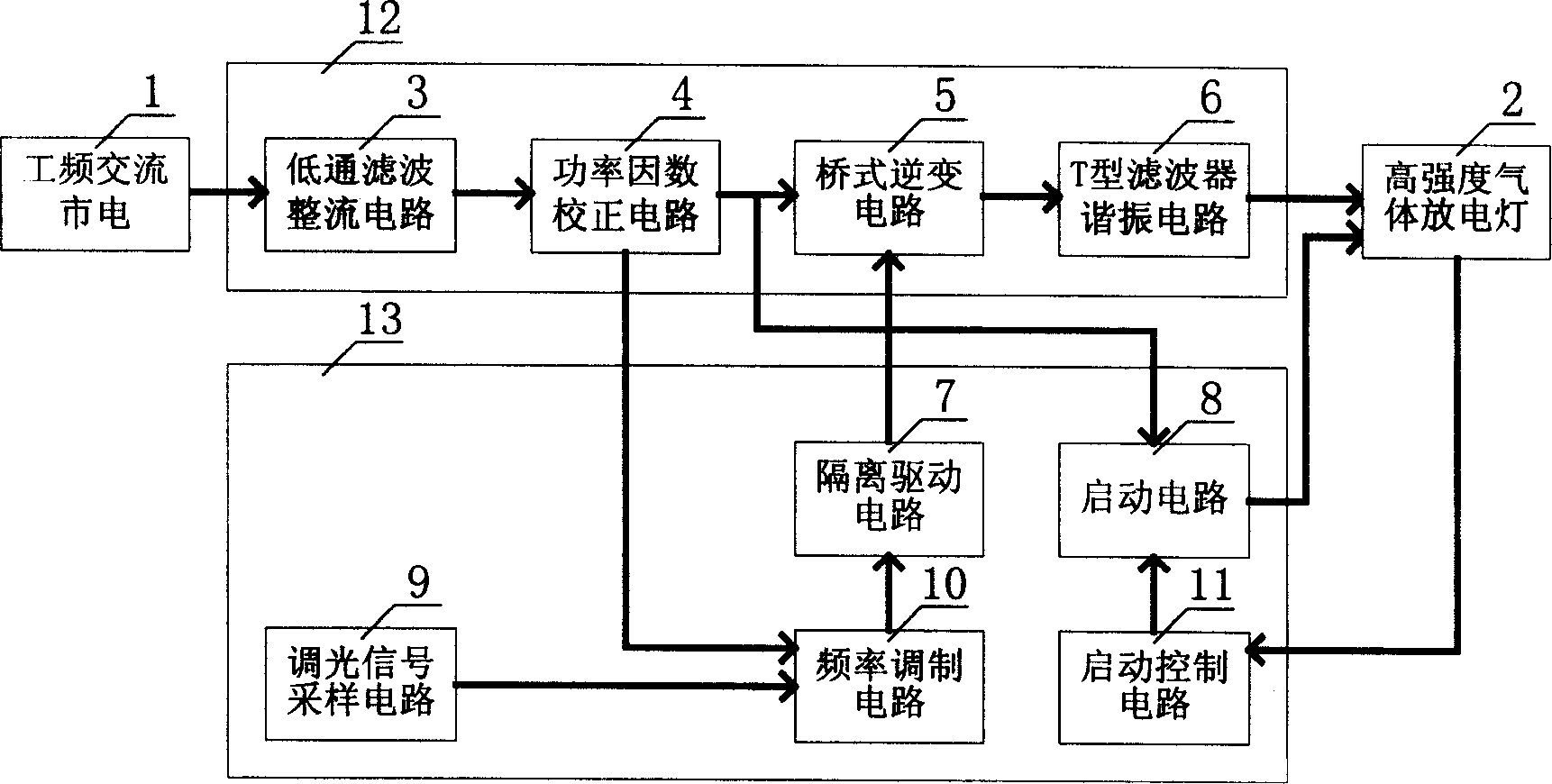
[0023] Specific embodiment 1: The electronic ballast for dimming high-intensity gas discharge lamps includes a gas discharge lamp main circuit 12 connected to the high-intensity gas discharge lamp 2 and a control circuit 13 connected to the gas discharge lamp main circuit. The main circuit of the gas discharge lamp is composed of a low-pass filter rectifier circuit 3, a power factor correction circuit 4, a bridge inverter circuit 5, and a T-type filter resonance circuit 6. The control circuit is a dimming signal sampling circuit 9 , Frequency modulation circuit 10, isolation drive circuit 7, start control circuit 11, start circuit 8; the low-pass filter rectifier circuit 3, power factor correction circuit 4, bridge inverter circuit 5, T-type filter resonance The circuit 6 is connected in sequence between the power frequency AC mains 1 and the high-intensity gas discharge lamp 2; the dimming signal sampling circuit 9 is connected to the frequency modulation circuit 10, the power fa...

specific Embodiment 2

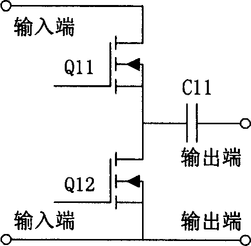
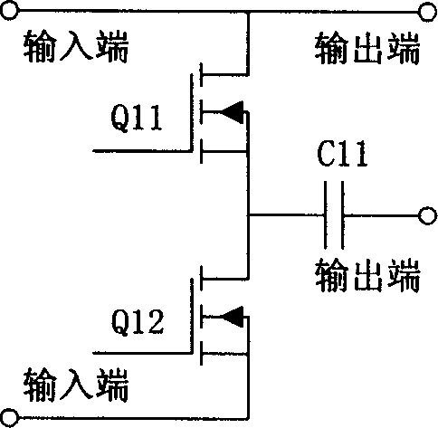
[0029]Specific embodiment 2: The electronic ballast for dimming high-intensity gas discharge lamps described in embodiment 1, wherein the bridge inverter circuit 5 adopts: consisting of switching tubes Q21, Q22, capacitors C21, C22; switching tubes Q21 and the output terminal of the switching tube Q22 are connected in series; the capacitor C21 and the capacitor C22 are connected in series; the output terminals of the switching tubes Q21 and Q22 are connected in series and the capacitors C21 and C22 are connected in series in parallel; the output terminals of the switching tubes Q21 and Q22 are connected in series with the capacitor The two ends of C21 and C22 in series and the two ends in parallel are the input ends; the middle end of the output ends of the switch tubes Q21 and Q22 in series and the middle end of the series capacitors C21 and C22 are the output ends of a half-bridge inverter circuit.

specific Embodiment 3

[0030] Specific embodiment 3: In the electronic ballast for dimming high-intensity gas discharge lamps described in embodiment 1, the bridge inverter circuit 5 adopts a full-bridge inverter circuit: switch tubes Q31, Q32, Q33, Q34 constitutes; the output terminals of the above-mentioned switching tubes Q31 and Q32 are connected in series, the output terminals of the switching tubes Q33 and Q34 are connected in series, and the output terminals of the switching tubes Q31 and Q32 are connected in series and the output terminals of the switching tubes Q33 and Q34 are connected in series and connected in parallel. The output terminal of Q32 is connected in series with the output terminals of Q33 and Q34, and the output terminal of Q32 is connected in series. The output terminals of Q31 and Q32 are connected in series, and the output terminals of Q33 and Q34 are connected in series. The output terminal.


PUM


Abstract

The invention relates to a dimming electronic ballast used in high strength discharge lamp and a method for selecting its working frequency. It comprises major loop of gas discharge lamp and control circuit connected with the major loop, where the major loop is composed of rectifier circuit with lowpass filter, PFC correction circuit, bridge inverter circuit and T-filter resonant circuit. It regulates the working frequency of switch tube of the bridge inverter circuit to make the working frequency greater than the upper limit frequency of sound resonance as the high strength gas discharge lamp outputs rating power and the working frequency of the high strength gas discharge lamp in the dimming course greater than the working frequency at the time of the high strength gas discharge lamp outputting the rating power.

Description

Technical field [0001] The invention belongs to the technical field of applied electronics, and relates to a dimming electronic ballast for high-intensity gas discharge lamps and a method for selecting its working frequency. Background technique [0002] High intensity discharge lamps (HID) mainly include metal halide lamps (MHL), high pressure sodium lamps (HPS), high pressure mercury lamps, and some special gas discharge lamps such as xenon lamps and krypton lamps. HID lamps have the advantages of small size, high luminous efficiency, good color rendering, long life, etc., and have become the third generation of electric light sources after incandescent lamps and fluorescent lamps. Electronic ballasts have the advantages of high power factor, high efficiency, small size, light weight, no noise, no flicker, etc., and will gradually replace traditional inductive ballasts. However, for high-intensity gas discharge lamps, especially metal halide lamps, ther...

Claims


Application Information

Patent Timeline
Patent Type & Authority Applications(China)
IPC IPC(8): H05B41/288
CPCY02B20/202Y02B20/00
Inventor 姜轶峰陈敏黄秋凯沈淼森钱照明
Owner ZHEJIANG UNIV
Why Eureka
Try Eureka